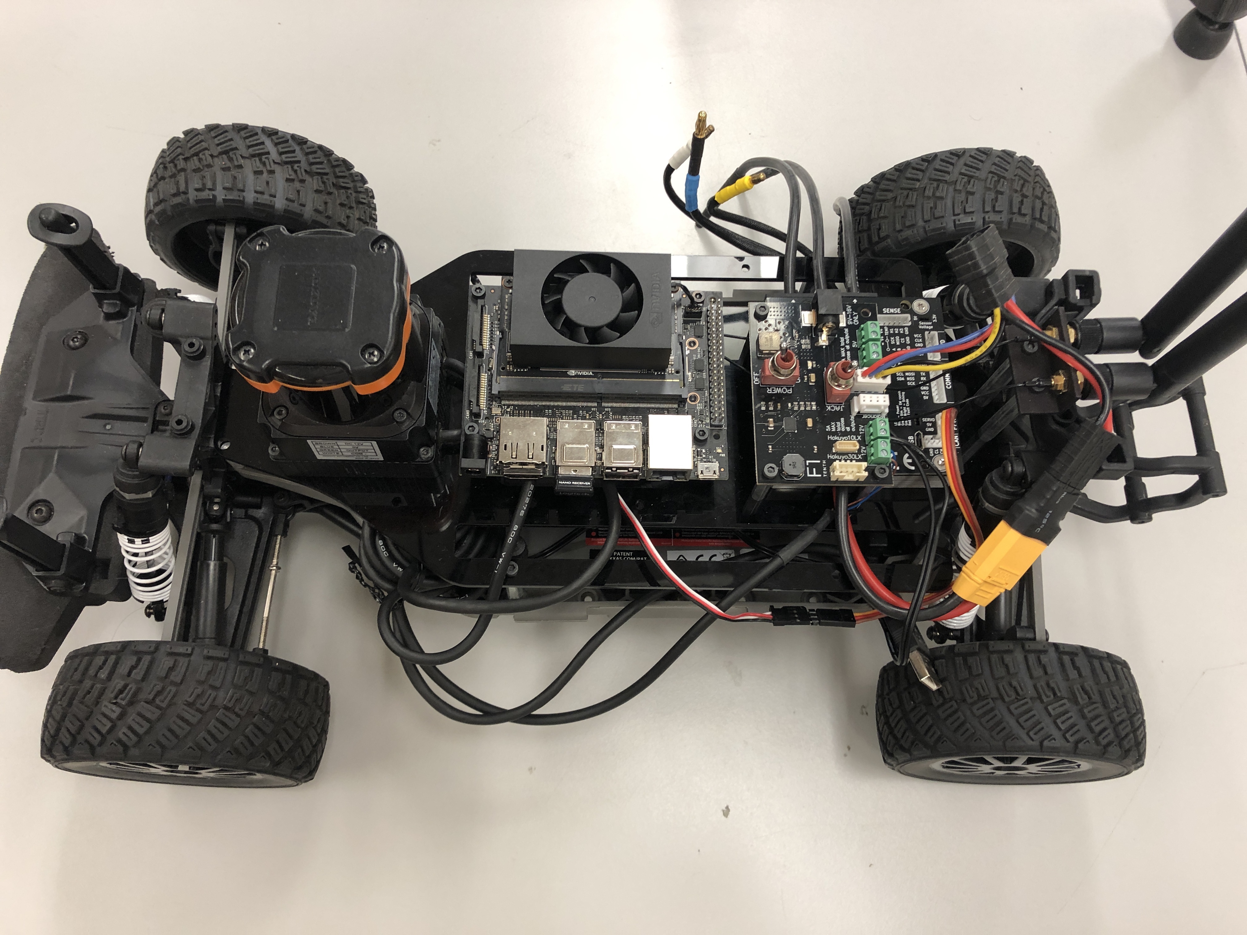
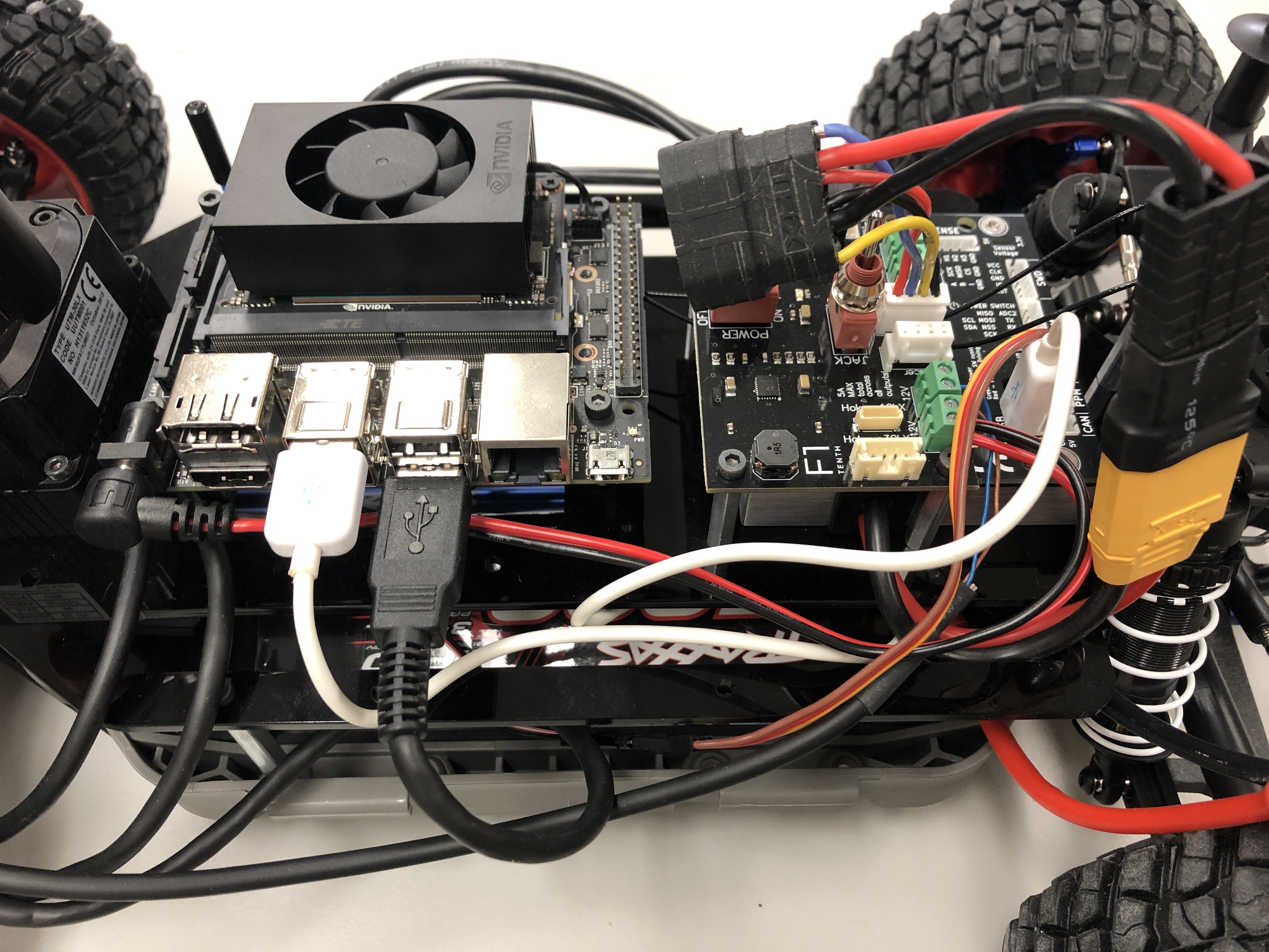
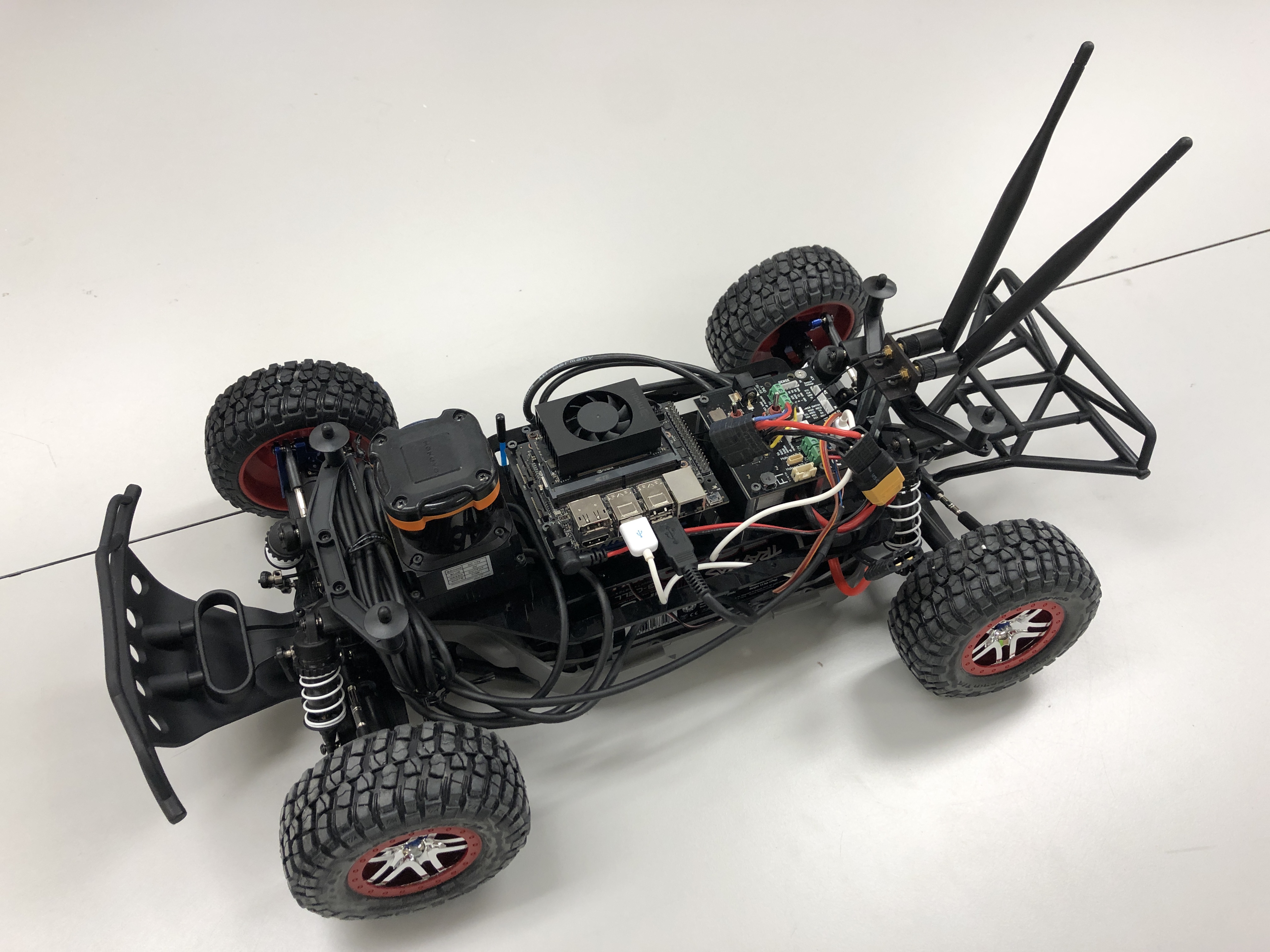
Now that we have the autonomy elements attached to the upper level chassis, we are going to attach the upper level chassis to the lower level chassis. This part may be a tad unwieldy due to the amount of wires and cables that have to be contained. The complete process for the last hardware part can be watched in this video tutorial too.
1. Mounting the Upper Level Chassis to the Lower Level Chassis
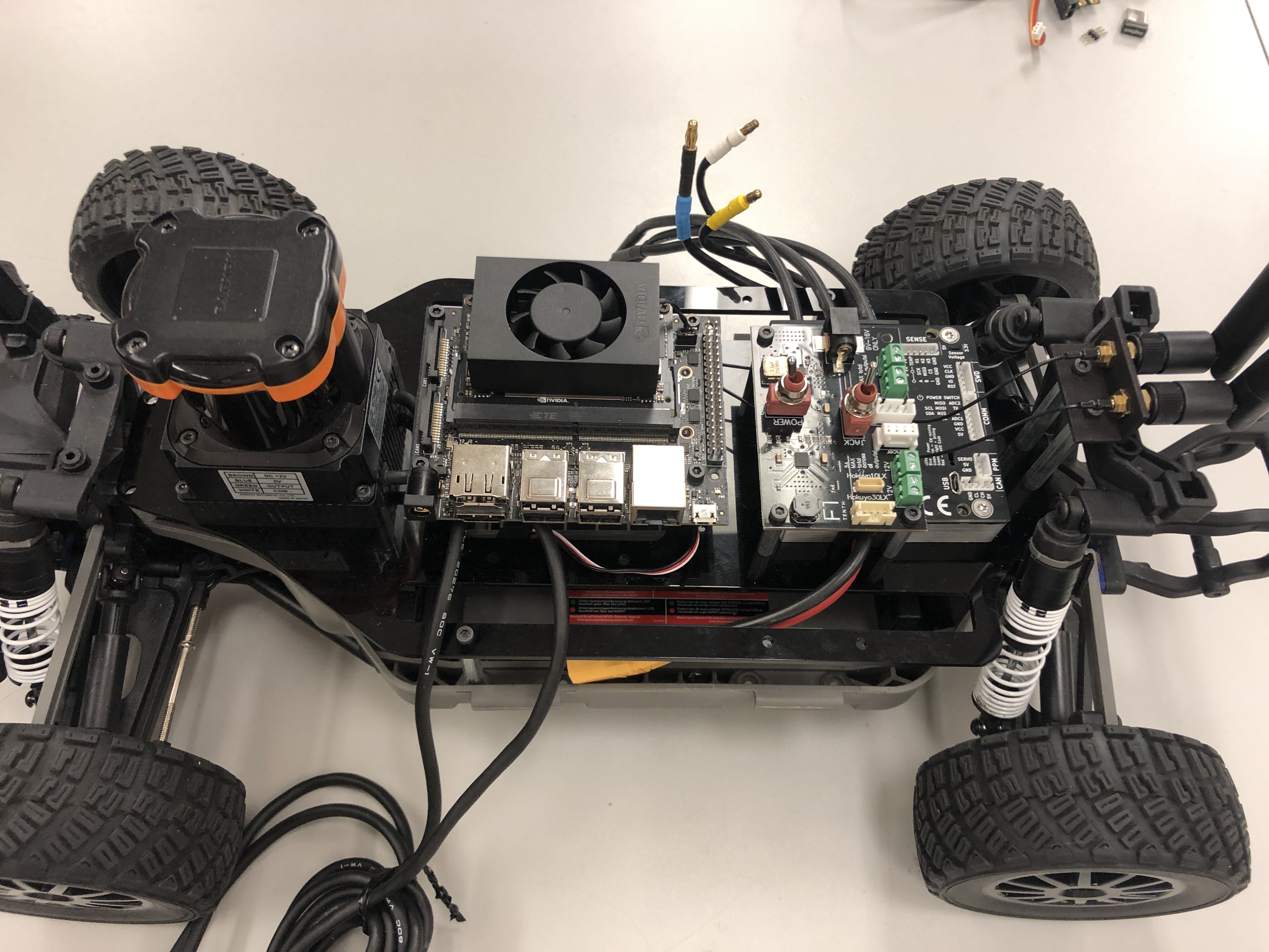
Gently place the upper level chassis on top of the standoffs of the lower level chassis. The VESC should be towards the back of the car. Thread the PPM cable from the lower level chassis, through one of the Platform Deck slot.
Upper Level Chassis gently placed on top of Lower Level Chassis.
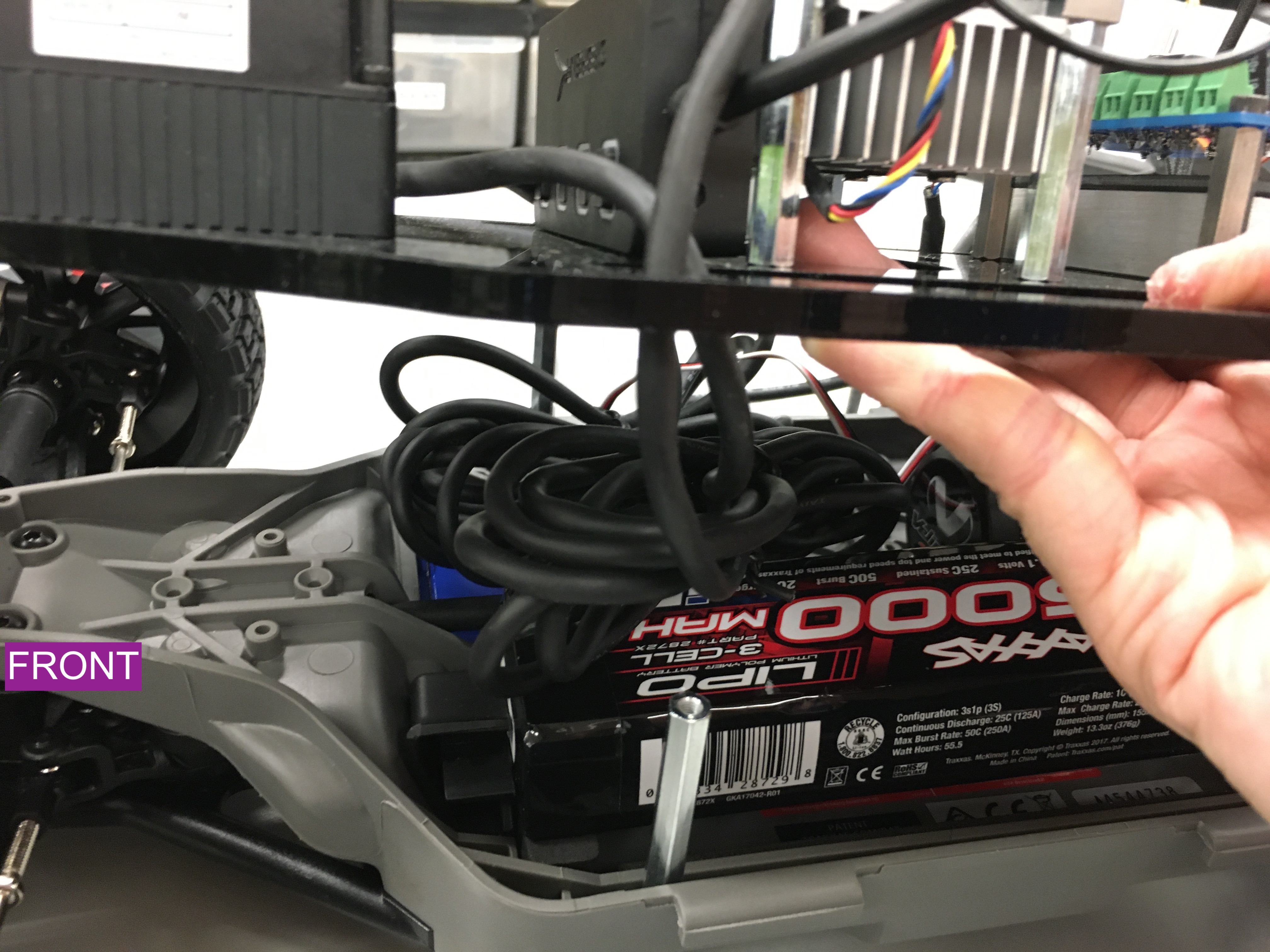
Lidar cables carefully arranged on top of battery.
Use three M3 x 10mm (these are the ones that were removed from the chassis during the Lower Level Chassis build section) screws to attach the Platform Deck to the standoffs on the lower level chassis.
It may be useful to use a zip tie to secure the USB cable from the lidar to the platform.
Danger
The driveshaft that runs along the length of the chassis rotates when the car moves. You can manage the cables and wires in whatever manner you like but make sure that you keep them away from any rotating assemblies, including the driveshaft. If you don’t, then the rotating assemblies will pull on all the cables and the last 1-2 hours of your life will have been in vain.
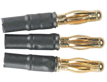
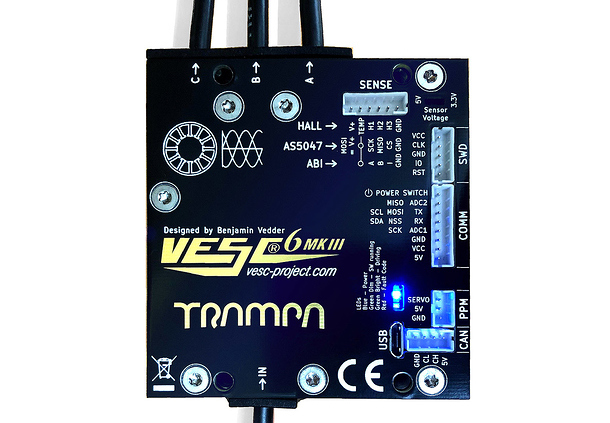
Now, we are going to connect these to the VESC. This part is a tad tricky.
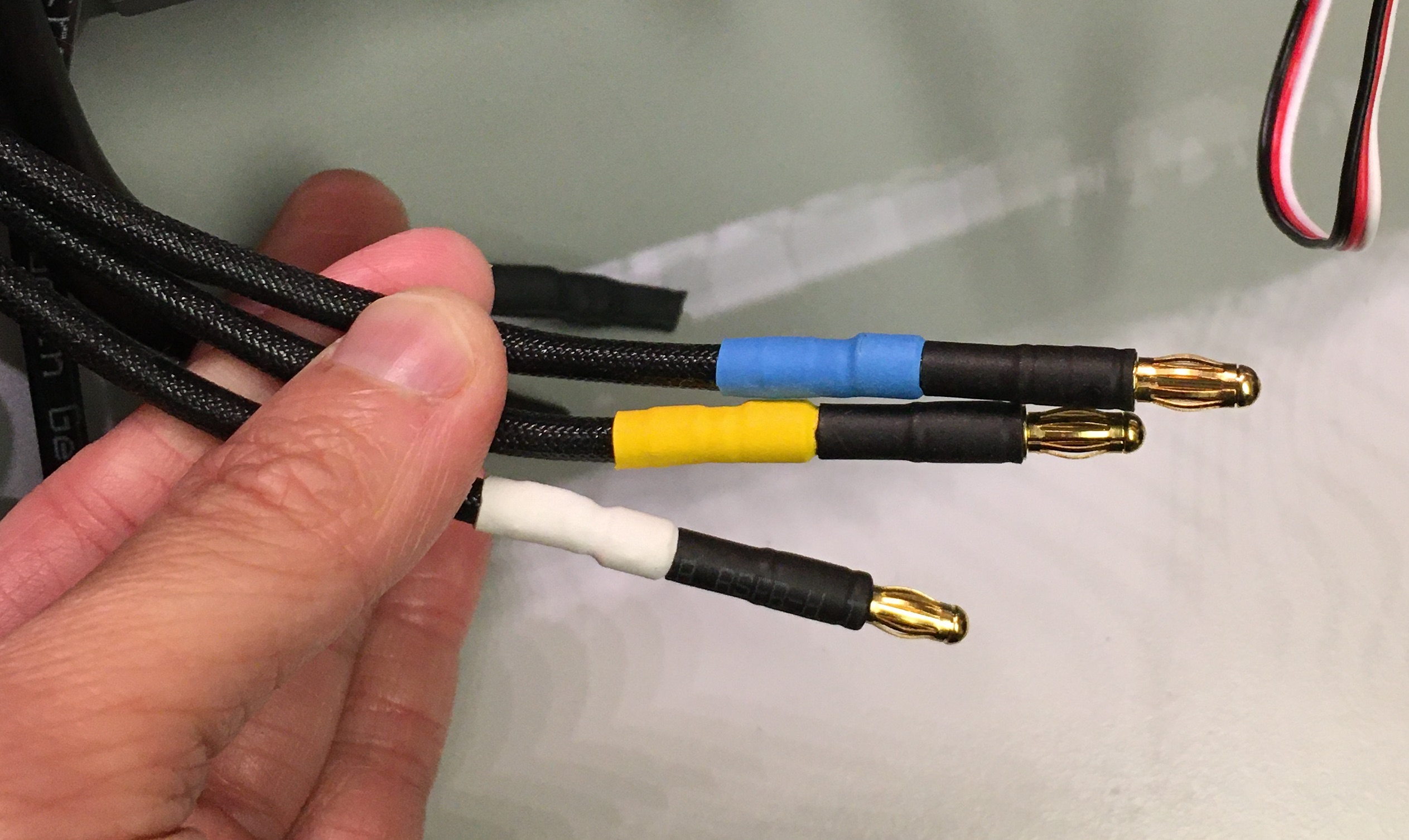
A -> WHITE
B -> YELLOW
C -> BLUE
Brushless Motor wires connected to the Bullet Adapters then connceted to the VESC wires.
Important
After you flash the firmware on the VESC, if the vehicle runs backwards to the expected motion, simply swap the WHITE wire to “C” and BLUE wire to “A”.
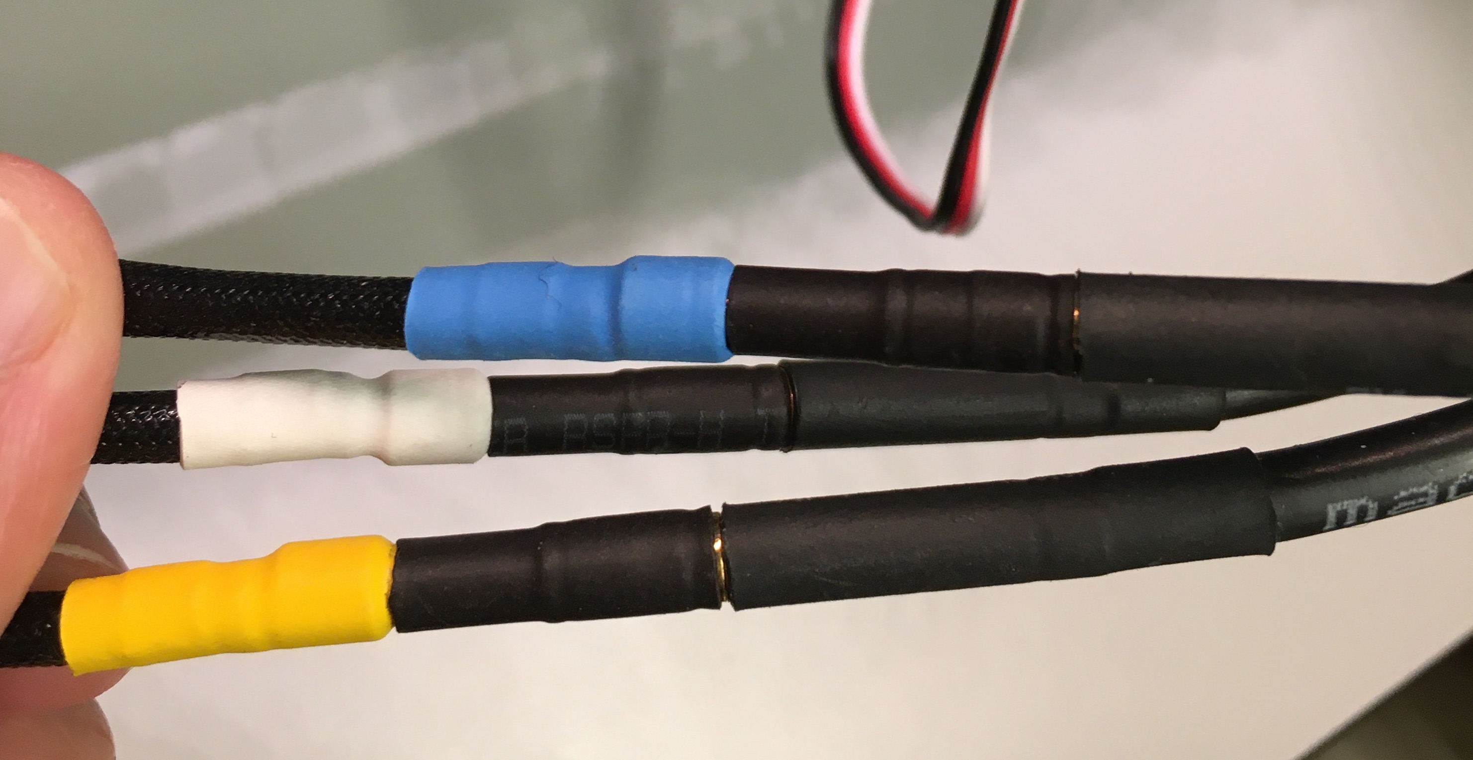
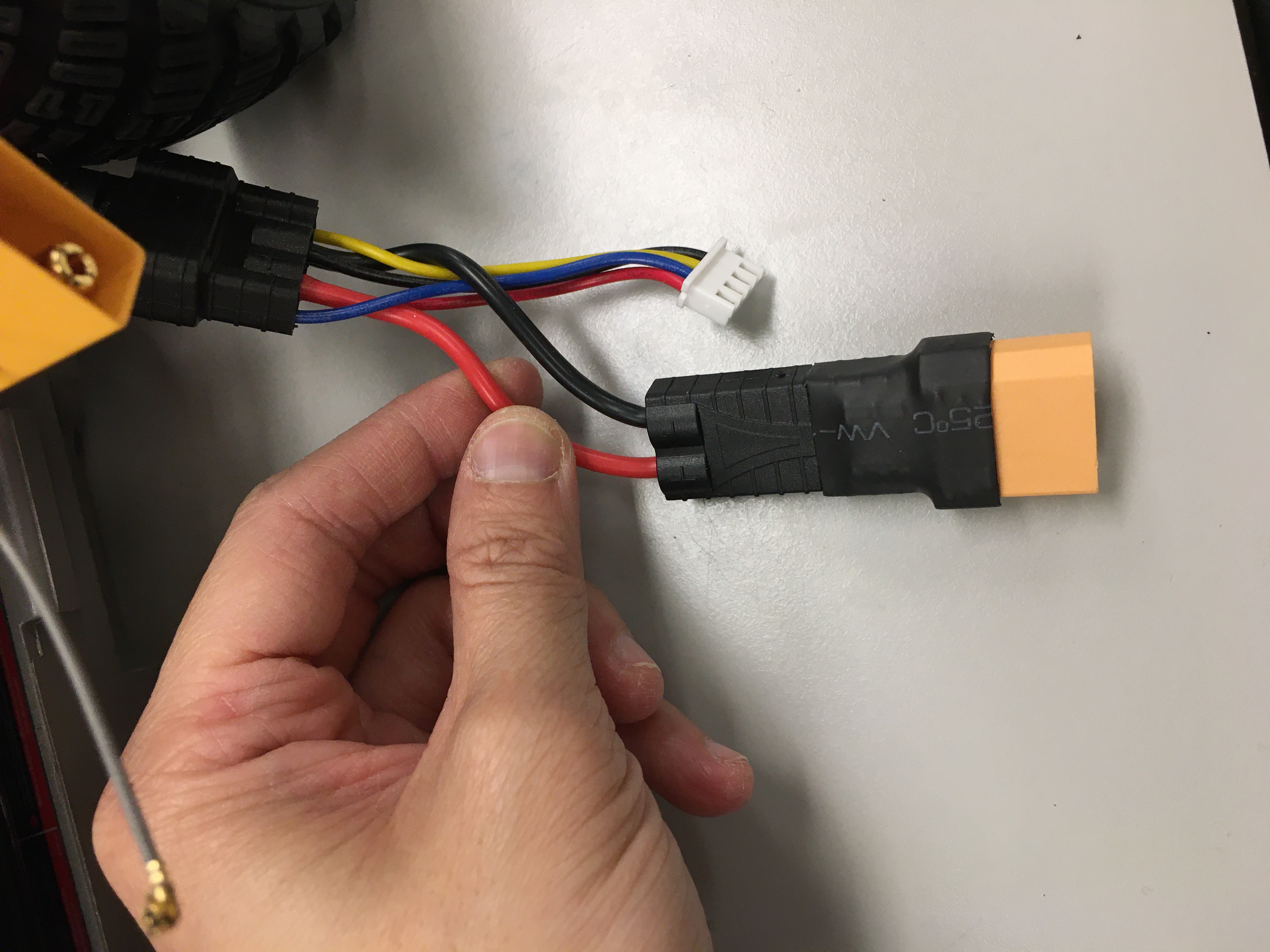
MAKE SURE THAT RED/POWER AND BLACK/GROUND ARE CONNECTED CORRECTLY TO THE RED/POWER AND BLACK/GROUND OF THE CHARGE ADAPTER Fire will happen if this is plugged backwards.
Charge adapter cable plugged into the Lipo battery.
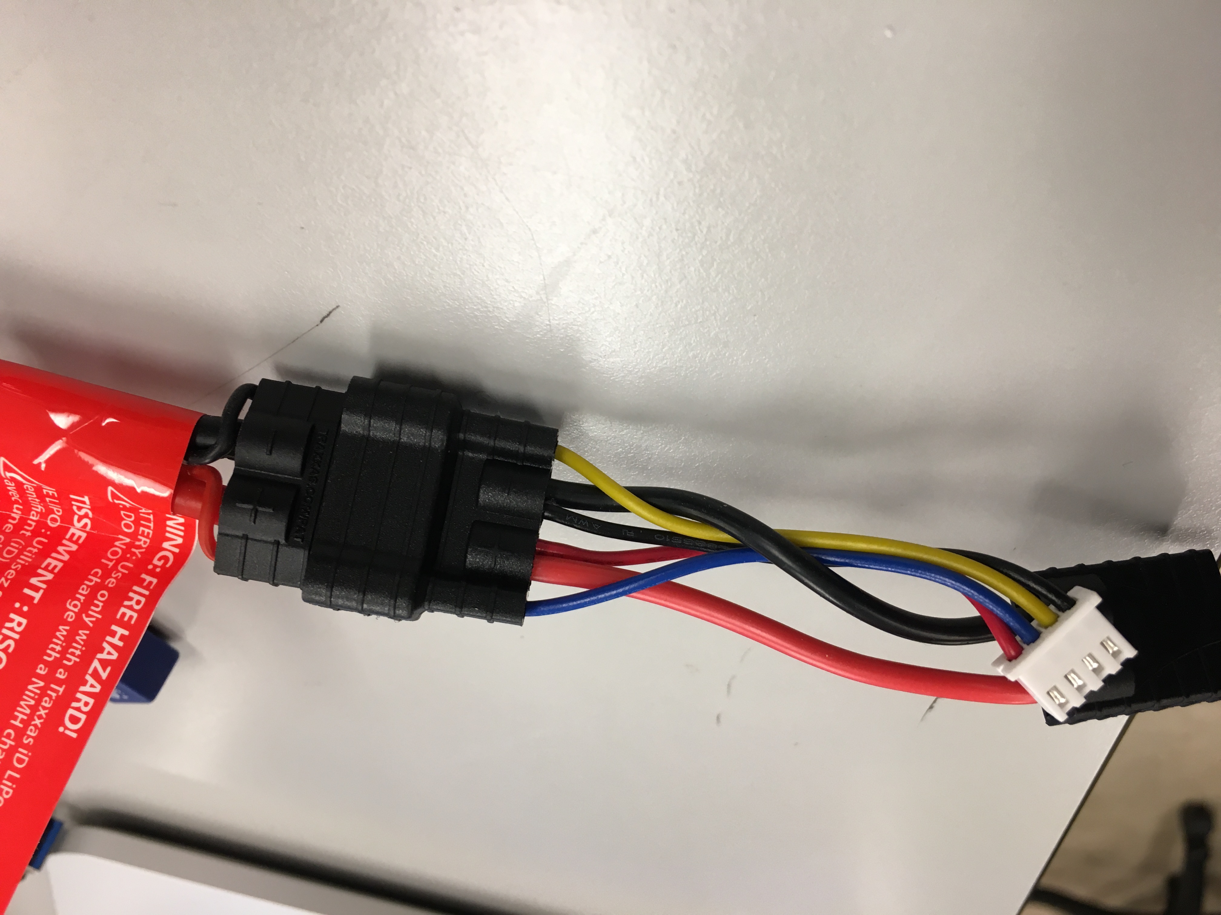
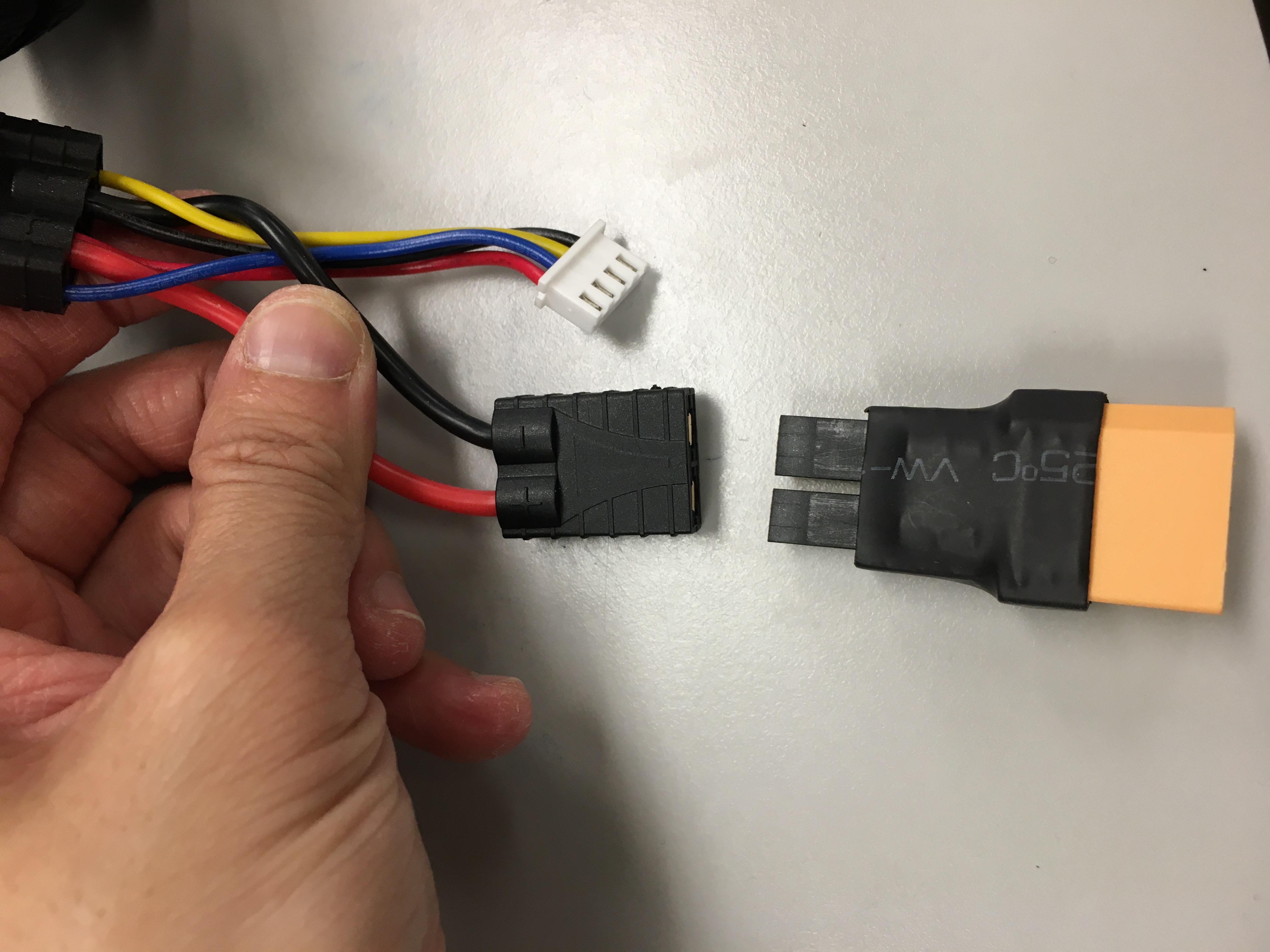
Then, connect the other side of the charge adapter to a TRX to XT90 adapter.
The NVIDIA Jetson NX needs to be connected to the powerboard. Use the barrel jack to pig tail connector. The board uses a 2.5x5.5mm power jack (MFN: PJ-036BH-SMT-TR). It is an unfortunate fact of life that the connections for barrel jacks are not standarized. For the specific barrel jack on this board, the center pin is POWER. Do not plug in a power supply whose center pin is ground. Connect one of the ends of the cable with GND on the powerboard, the other one with the 12V connector. Afterwards you can plug in the barrel jack in the NVIDIA Jetson NX.
NVIDIA Jetson power supply connected with the powerboard.
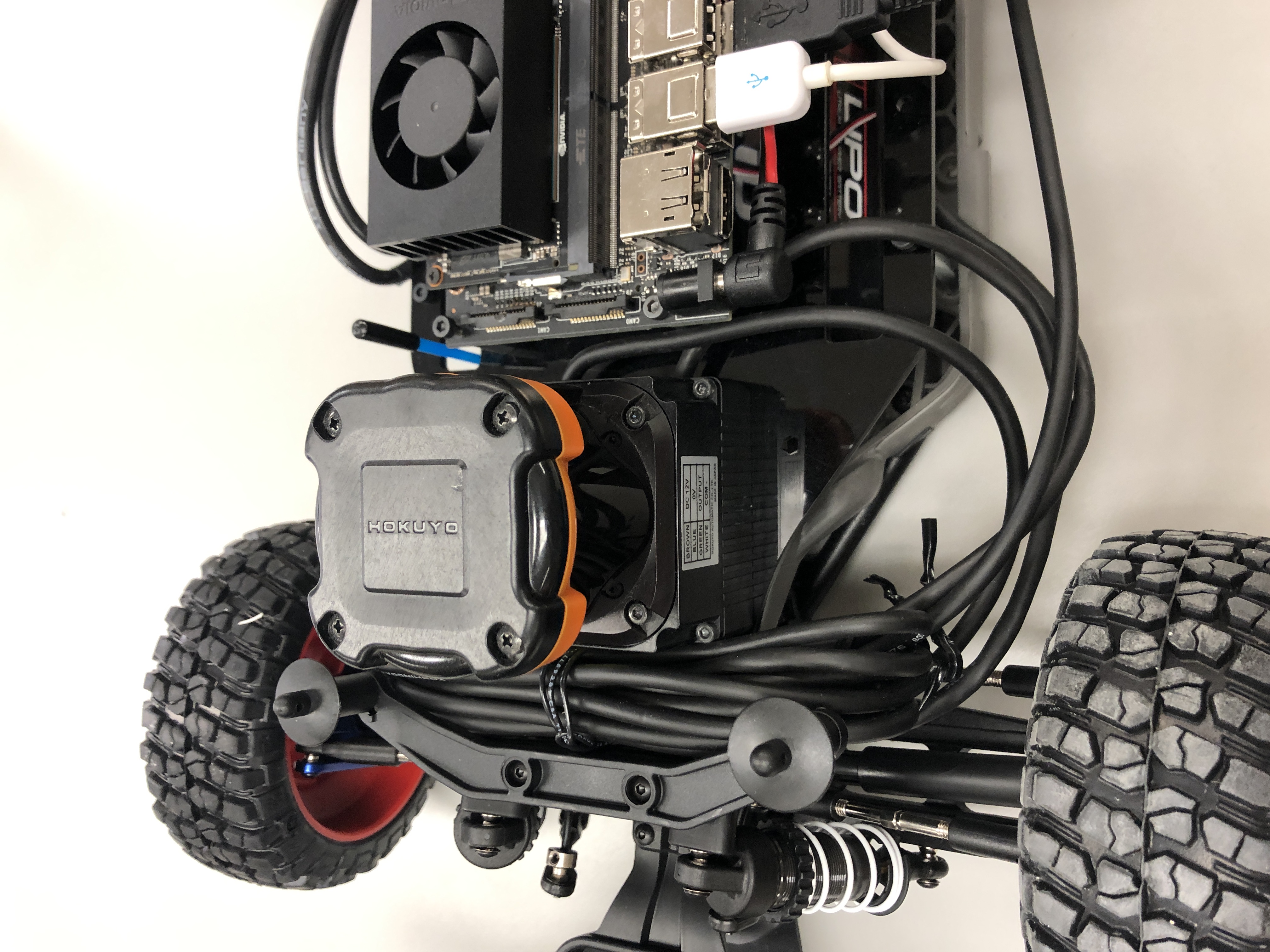
The lidar comes with two very long cables. We are going to try out best to manage them. Split the two cables of the lidar and loop them under the slots on the Platform Deck.
Storing the USB Lidar Cable in front of the Lidar
Using a twist tie, rubber band, or zip tie, gather the majority of the cables on each side. Then connect the Lidar to the NVIDIA Jetson. If using the UTM-30LX, plug the USB into one of the ports of the NVIDIA Jetson USB hub. If you are using a 10LX, plug it into the ethernet port of the Jetson NX.
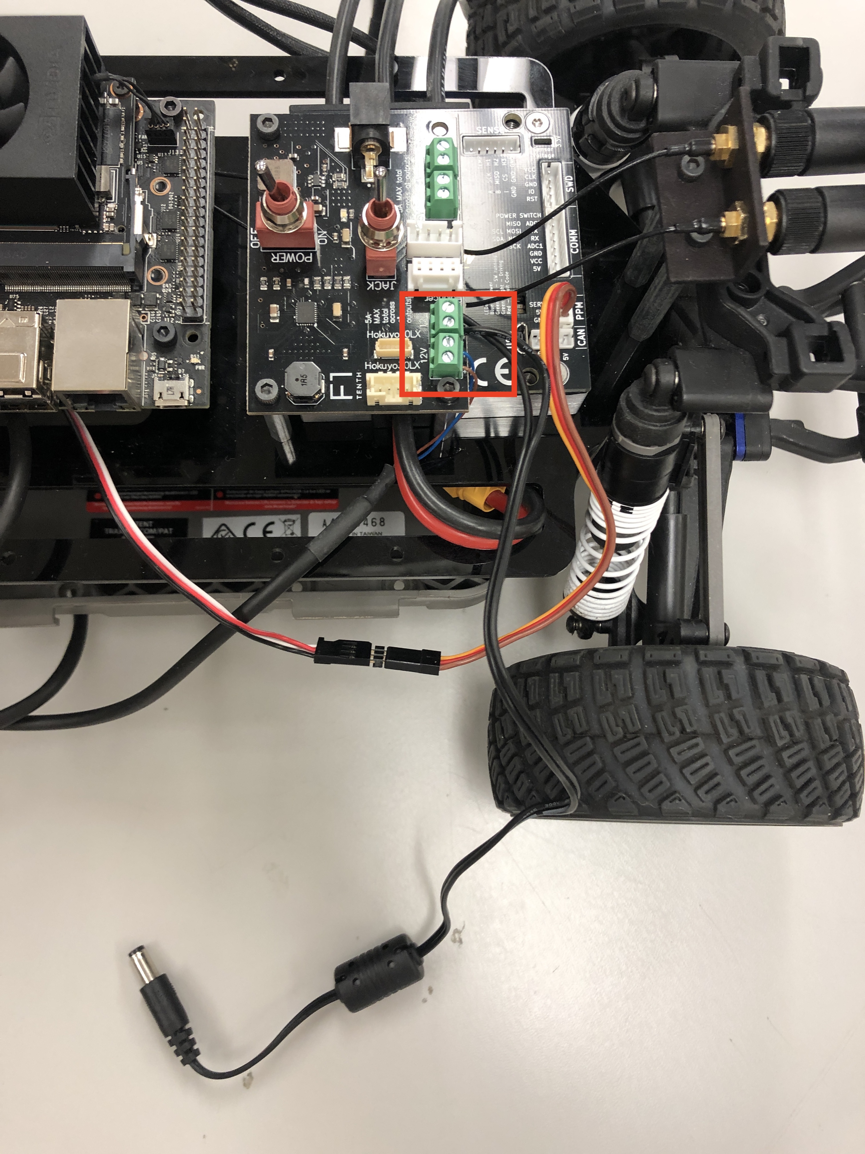
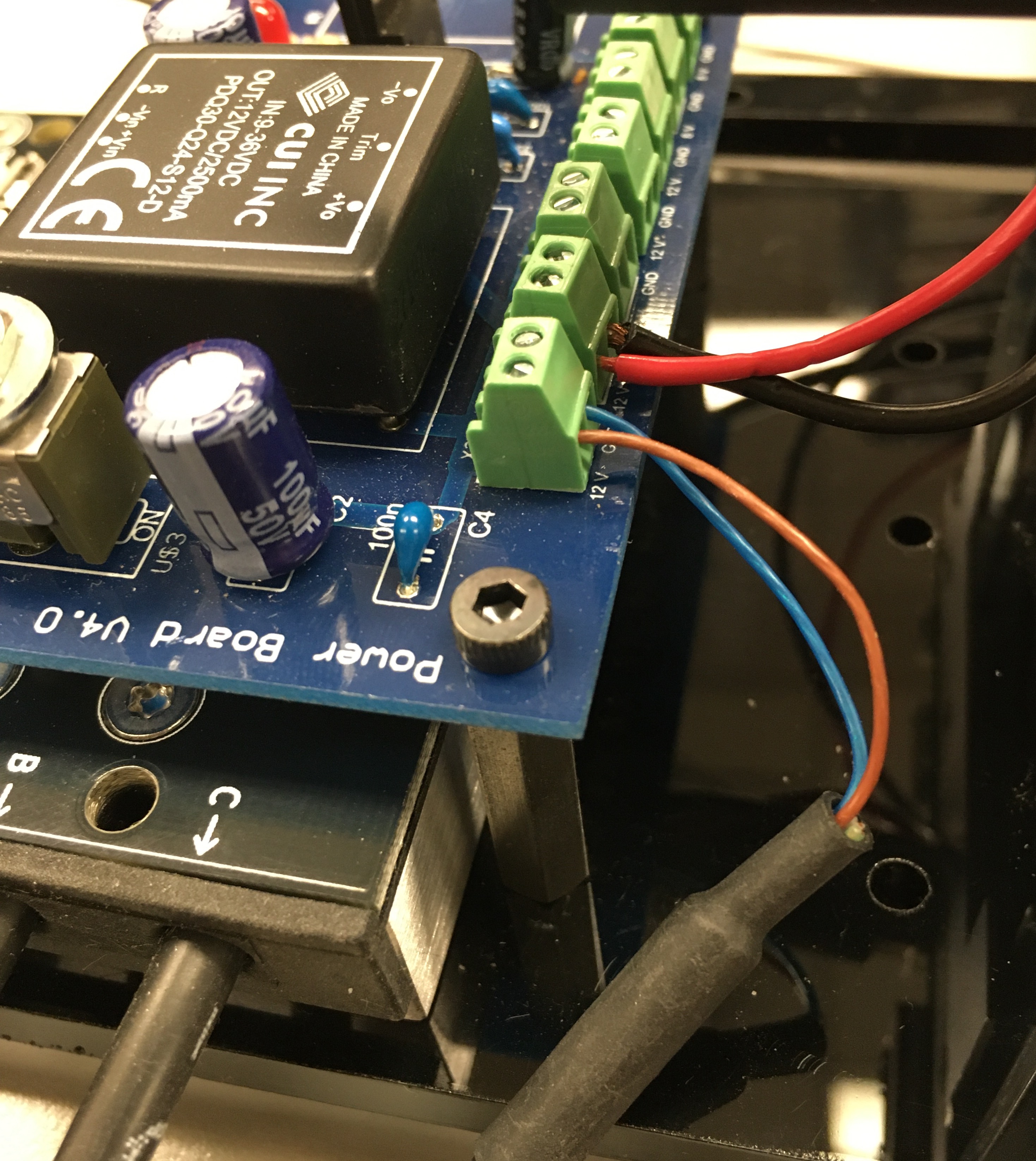
Then its time to provide the energy connection for the Lidar. For the stripped cable side, insert the BROWN (POWER) and BLUE (GROUND) wires into one of the 12V terminal blocks on the Powerboard.
Danger
*BROWN is POWER and BLUE is GROUND.* DO NOT MIX THESE UP OTHERWISE YOU WILL FRY YOUR VERY EXPENSIVE LIDAR. And then life will be very very sad. When in doubt, check the side of the Hokuyo. It will list out the correspondence of each wire.
Lidar power is plugged into the terminal block with Brown to Power and Blue to Ground.
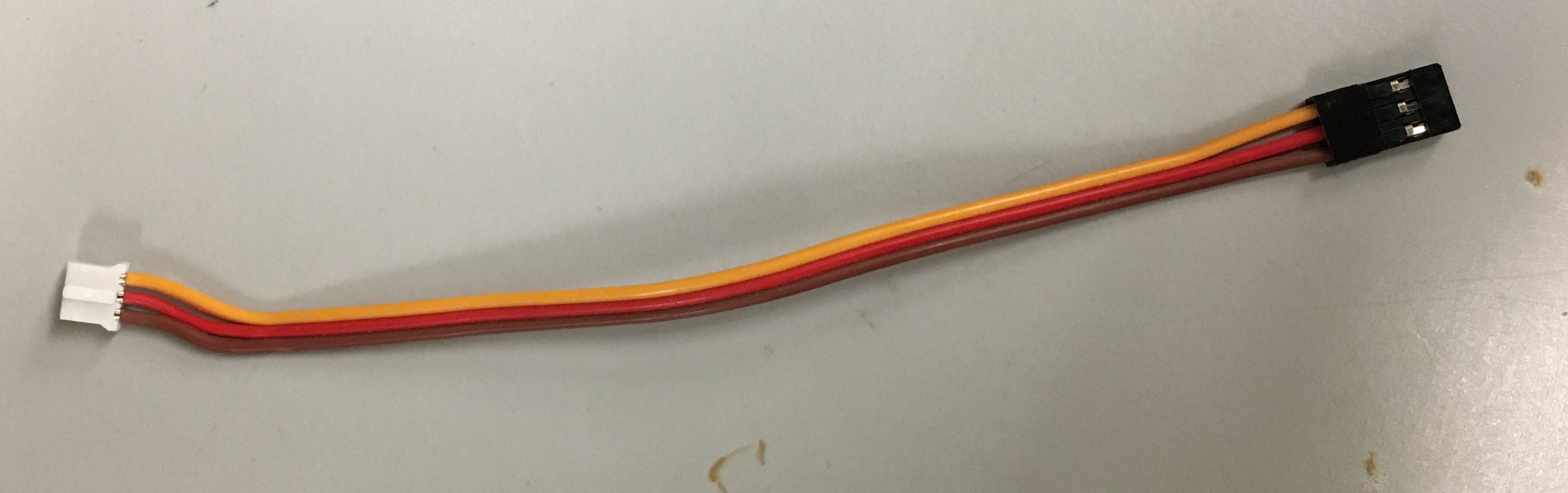
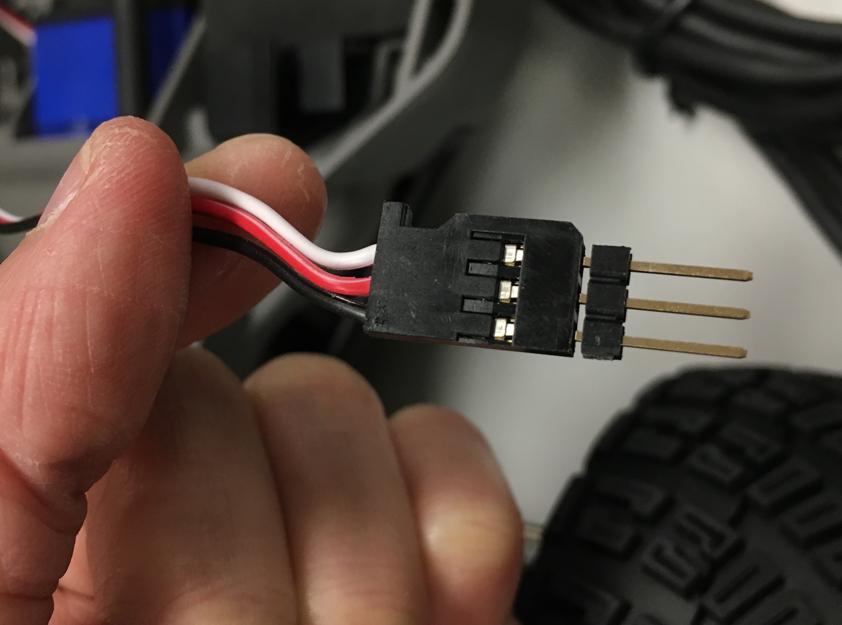
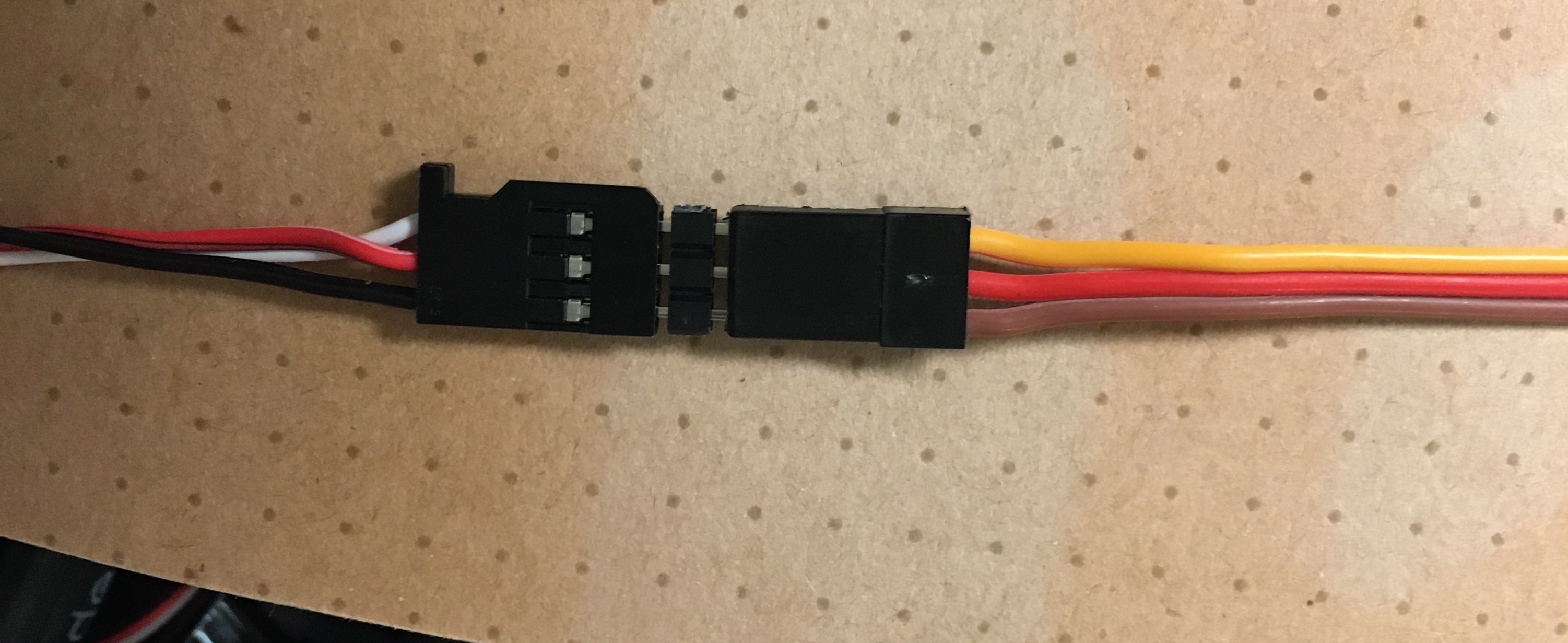
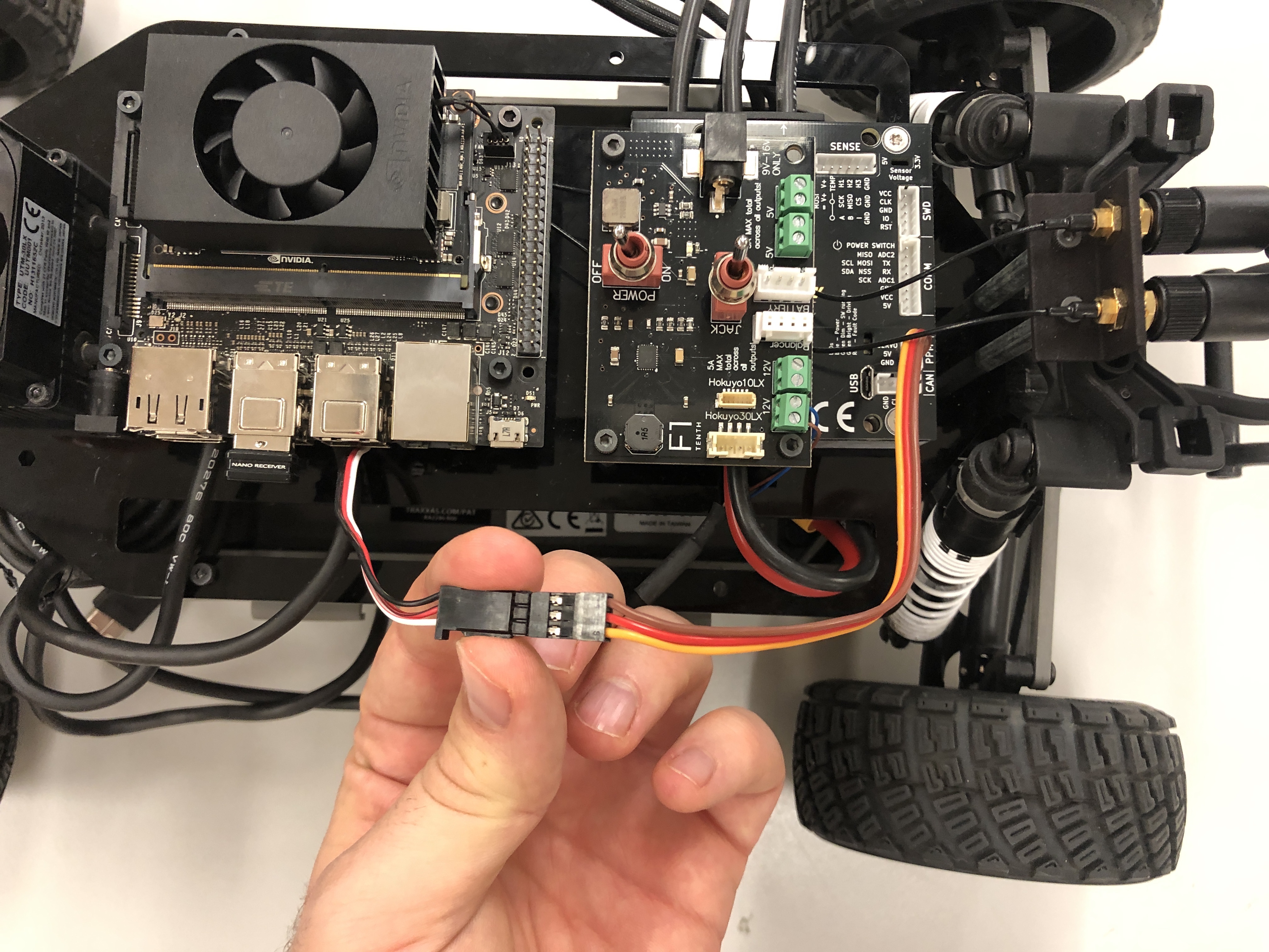
Now we are going to connect the PPM (Pulse-Position Modulation) cable to the Servo. The PPM cable connects the Servo to the VESC, which we will install on the Upper Level Chassis later.
PPM cable. Note that it has a white end and a black end.
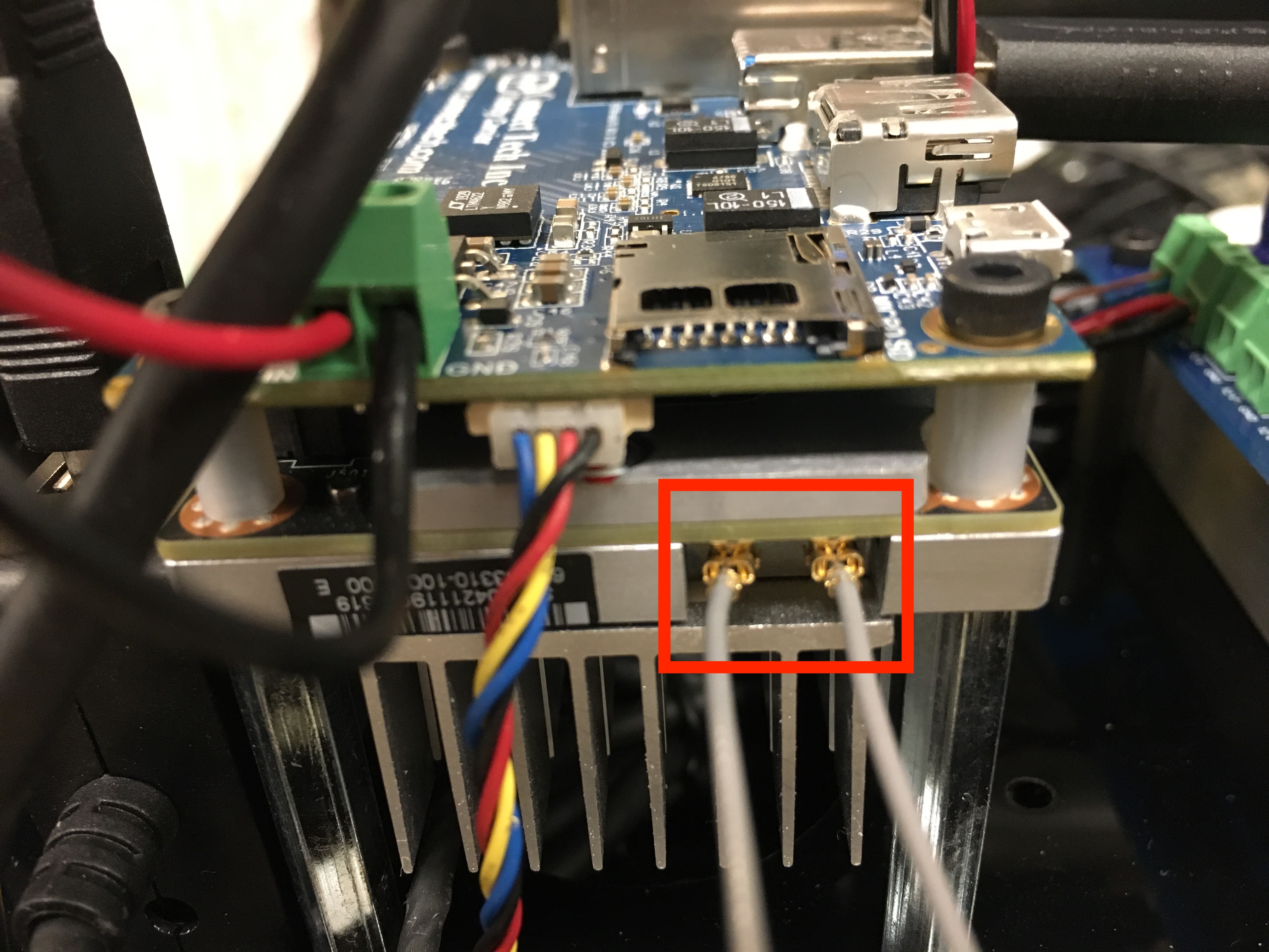
Attach the two wires for the Jetson Wi-Fi antenna to the two gold-colored connectors near the fan connector on the heat sink (the order of the wires doesn’t matter). This can be a little tricky, so you might want to use a flathead screwdriver to ensure the connections are tight. Don’t press too hard , however as you can easily damage the connectors if you use excessive force!