Advanced Information
RVIZ Visualization
With the simulator running, open rviz.
In the left panel at the bottom click the Add button, then in the By topic tab add the /map topic and the /scan topic.
Then in the By display type tab add the RobotModel type.
In the left panel under the newly added LaserScan section, change the size to 0.1 meters for a clearer visualization of the lidar (shown in rainbow).
You can use a keyboard or USB joystick to drive the car around, or you can place the car manually by clicking the 2D Pose Estimate button on the top of the screen and dragging your mouse on the desired pose.
ROS API
The simulator was set up with two main objectives in mind- similitude to the real car and fast prototyping of racing algorithms. The simulator node was written such that it can be swapped out with the RoboRacer car itself, and if all topic names remain the same, the same exact code can be run to drive the car. The rest of the ROS nodes are organized so that new planning algorithms can be added quickly and toggled between during driving.
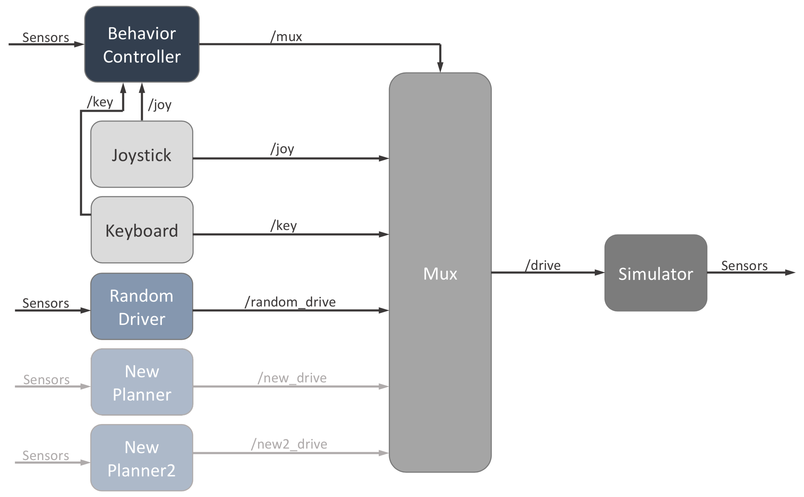
Simplified graph of ROS nodes
Our public simulator includes a simple random driver node as an example for what a planning node should look like. Each planner can listen to the sensor data published by the simulator and then publish AckermannDrive messages to their own specific topic (e.g., /random_drive). The mux node listens to all of these topics, then takes the message from whichever planner is turned on and publishes it to the main /drive topic, which the simulator listens to. Note that only the velocity and steering angle specified in the message are used. The mux node also listens to joystick and keyboard messages too, for manual driving.
The behavior controller node tells the mux node which planner is on through the /mux topic. By default, each planner (including keyboard and joystick) is mapped to a joystick button and keyboard key, and they are simply toggled on and off manually.
Additionally, upon collision, the car will halt and all mux channels will be clear- nothing will be in control until manual intervention.
To instantly move the car to a new state publish Pose messages to the /pose topic. This can be useful for scripting the car through a series of automated tests.
The simulated lidar is published to the /scan topic as LaserScan messages.
The pose of the car is broadcast as a transformation between the map frame and the base_link frame. base_link is the center of the rear axis. The laser frame defines the frame from which the lidar scan is taken and another transform is broadcast between it and base_link.
Changing the Behavior Controller
If you plan to change the behavior of the car beyond keyboard, joystick, or direct pose control, you will mostly be writing new code in new planning nodes and the behavior controller node. Steps for adding a new planner are detailed below. By default, the behavior controller listens to sensor messages, so you could write the controller such that the car switches autonomously between planners during a race depending on these dynamic inputs.
Adding a planning node
There are several steps that necessary to adding a new planning node. There is commented out code in each place that details exactly what to do. Here are the steps:
Make a new node that publishes to a new drive topic. Look at random_walk.cpp for an example
Launch the node in the launch file
simulator.launchMake a new
Channelinstance at the end of the Mux() constructor inmux.cppAdd if statement to the end of the joystick and keyboard callbacks (key_callback(), joy_callback) in
behavior_controller.cppIn
params.yaml, add the following:a new drive topic name
a new mux index
a new keyboard character (must be a single alphabet letter)
a new joystick button index
You’ll need to get the mux index and drive topic name in mux.cpp for the new Channel, and the keyboard character, mux index, and joystick button index will all need to be added as member variables in behavior_controller.cpp. Your planning node will obviously need the drive topic name as well.
Parameters
The parameters listed below can be modified in the params.yaml file.
Topics
drive_topic: The topic to listen to for autonomous driving.
joy_topic: The topic to listen to for joystick commands.
map_topic: The topic to listen to for maps to use for the simulated scan.
pose_topic: The topic to listen to for instantly setting the position of the car.
pose_rviz_topic: The topic to listen to for instantly setting the position of the car with Rviz’s “2D Pose Estimate” tool.
scan_topic: The topic to publish the simulated scan to.
distance_transform_topic: The topic to publish a distance transform to for visualization (see the implementation section below).
Frames
base_link: The frame of the car, specifically the center of the rear axle.
scan_frame: The frame of the lidar.
map_frame: The frame of the map.
Simulator Parameters
update_pose_rate: The rate at which the simulator will publish the pose of the car and simulated scan, measured in seconds. Since the dynamics of the system are evaluated analytically, this won’t effect the dynamics of the system, however it will effect how often the pose of the car reflects a change in the control input.
Car Parameters
wheelbase: The distance between the front and rear axle of the racecar, measured in meters. As this distance grows the minimum turning radius of the car increases.
width: Width of car in meters
max_speed: The maximum speed of the car in meters per second.
max_steering_angle: The maximum steering angle of the car in radians.
max_accel: The maximum acceleration of the car in meters per second squared.
max_steering_vel: The maximum steering angle velocity of the car in radians per second.
friction_coeff: Coefficient of friction between wheels and ground
mass: Mass of car in kilograms
Lidar Parameters
scan_beams: The number of beams in the scan.
scan_field_of_view: The field of view of the lidar, measured in radians. The beams are distributed uniformly throughout this field of view with the first beam being at -scan_field_of_view and the last beam being at scan_field_of_view. The center of the field of view is direction the racecar is facing.
scan_distance_to_base_link: The distance from the lidar to the center of the rear axle (base_link), measured in meters.
scan_std_dev: The ammount of noise applied to the lidar measuredments. The noise is gaussian and centered around the correct measurement with standard deviation scan_std_dev, measured in meters.
map_free_threshold: The probability threshold for points in the map to be considered “free”. This parameter is used to determine what points the simulated scan hits and what points it passes through.
Joystick Parameters
joy: This boolean parameter enables the joystick if true.
joy_speed_axis: The index of the joystick axis used to control the speed of the car. To determine this parameter it may be useful to print out the joystick messages with rostopic echo /joy.
joy_angle_axis: The index of the joystick axis used to control the angle of the car. To determine this parameter it may be useful to print out the joystick messages with rostopic echo /joy.
joy_button_idx: The index of the joystick button used to turn on/off joystick driving.