1. Configuring the VESC
Danger
Important Safety Tips
Put your car on an elevated stand so that its wheels can turn without it going anywhere. If you don’t have an RC car stand, you can use the box that came with your Jetson.
Make sure you hold on to the car while testing the motor to prevent it from flying off the stand.
Make sure there are no objects (or people) in the vicinity of the wheels while testing.
Use a fully-charged LiPO battery instead of a power supply to ensure the motor has enough current to spin up.
- Equipment Required:
Fully built RoboRacer vehicle
Box or Car stand to put vehicle on
Laptop/computer (does not need to be running Linux)
Approximate Time Investment: 1 hour
The VESC is the electronic speed controller (motor controller) on the car — it drives the brushless motor and the steering servo based on the commands it receives from the Jetson. In this section you’ll install the VESC Tool, flash the VESC’s firmware, load the motor configuration, and tune the motor so the car drives correctly.
Note
If using the VESC mkIV, e.g. hardware based on VESC 4.12, see here for more details on how you can build your firmware for corresponding VESCs, and prebuilt firmware for different VESC hardware versions.
1. Installing the VESC Tool
We need to configure the VESC so that it works with our motor and vehicle transmission. Before you start, you’ll need to install the VESC Tool. You’ll have to register for an account to download. Add the free tier tool to cart (you don’t have to fill in any information other than your email.) After checkout, a download link will be sent to your email address. There should be versions of the software for Linux, Windows and macOS.
2. Powering the VESC
First we need to power the VESC. Plug the battery in, and make sure the polarity is correct. Note that you don’t need to turn on the Powerboard for configuring the VESC.
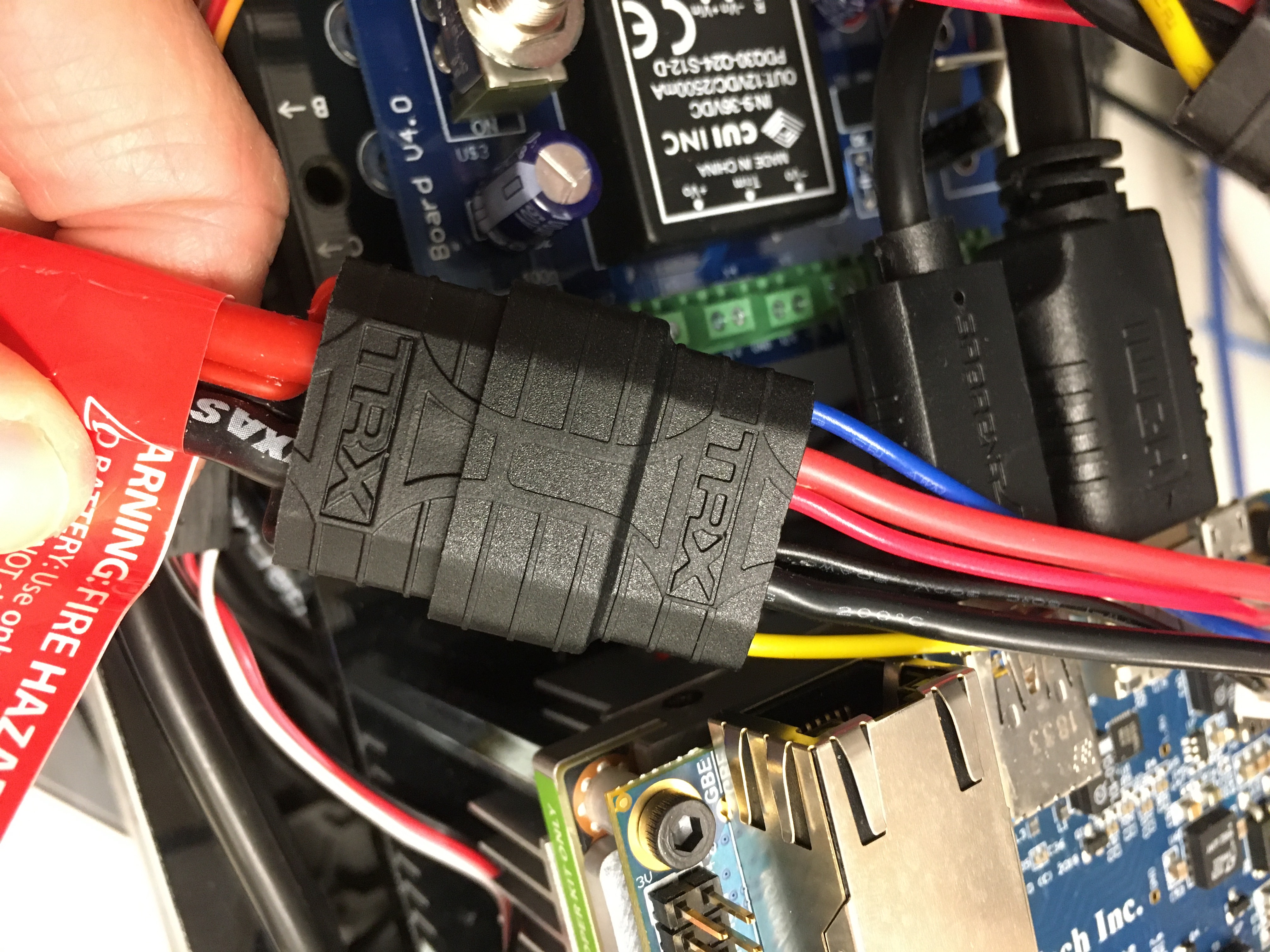
Plug the battery in, making sure the polarity is correct.
Next, unplug the USB cable of the VESC from the Jetson NX and plug the USB into your laptop that’s running the VESC Tool. You may want to use a longer cable.
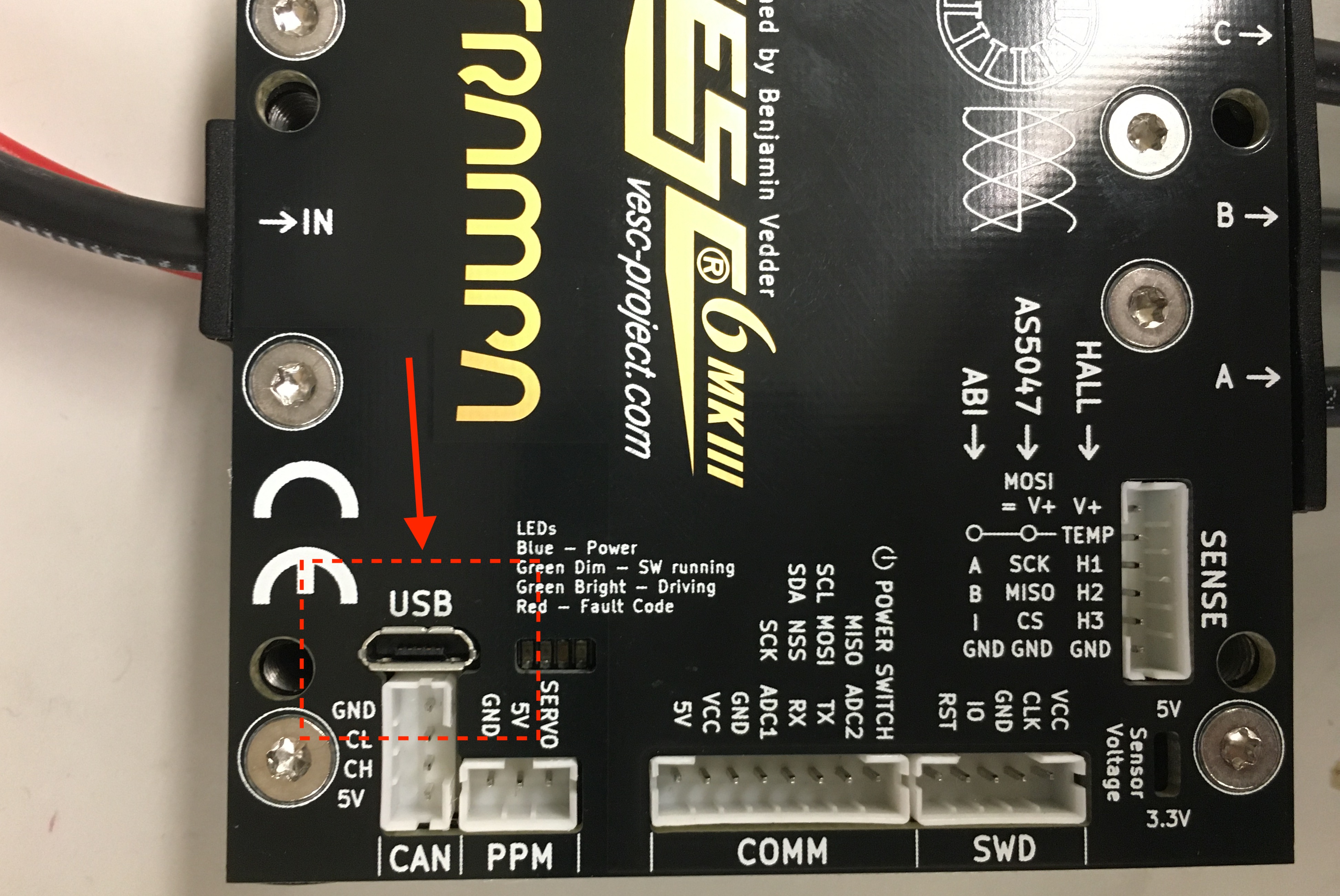
Plug a longer micro USB cable from the VESC to your computer.
3. Connecting the VESC to Your Laptop
Launch the VESC Tool. On the Welcome page, press the AutoConnect button on bottom left of the page. After the VESC is connected, you should see an updated status on the bottom right of the screen.
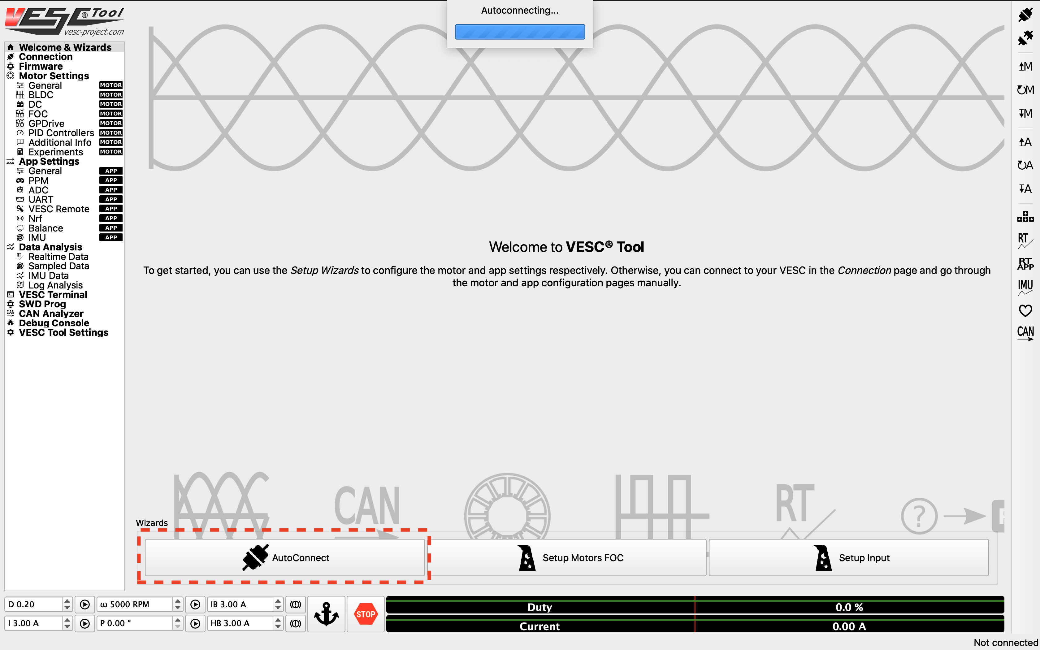
Click Autoconnect in the VESC Tool.
4. Updating the Firmware on the VESC
The first thing you’ll need to do is update the firmware onboard the VESC.
On the left side of the screen, click on the Firmware tab, then press the Download Latest button to download and flash the latest default firmware onto the connected VESC. A status bar at the bottom of the page will show the firmware update status. After it’s finished, the VESC will reboot and automatically reconnect.
Note
Older versions of this guide had you enable the Show non-default firmwares check box and select a VESC_servoout.bin option. With current versions of the VESC Tool that list comes up empty — use the Download Latest button to flash the latest default firmware instead.
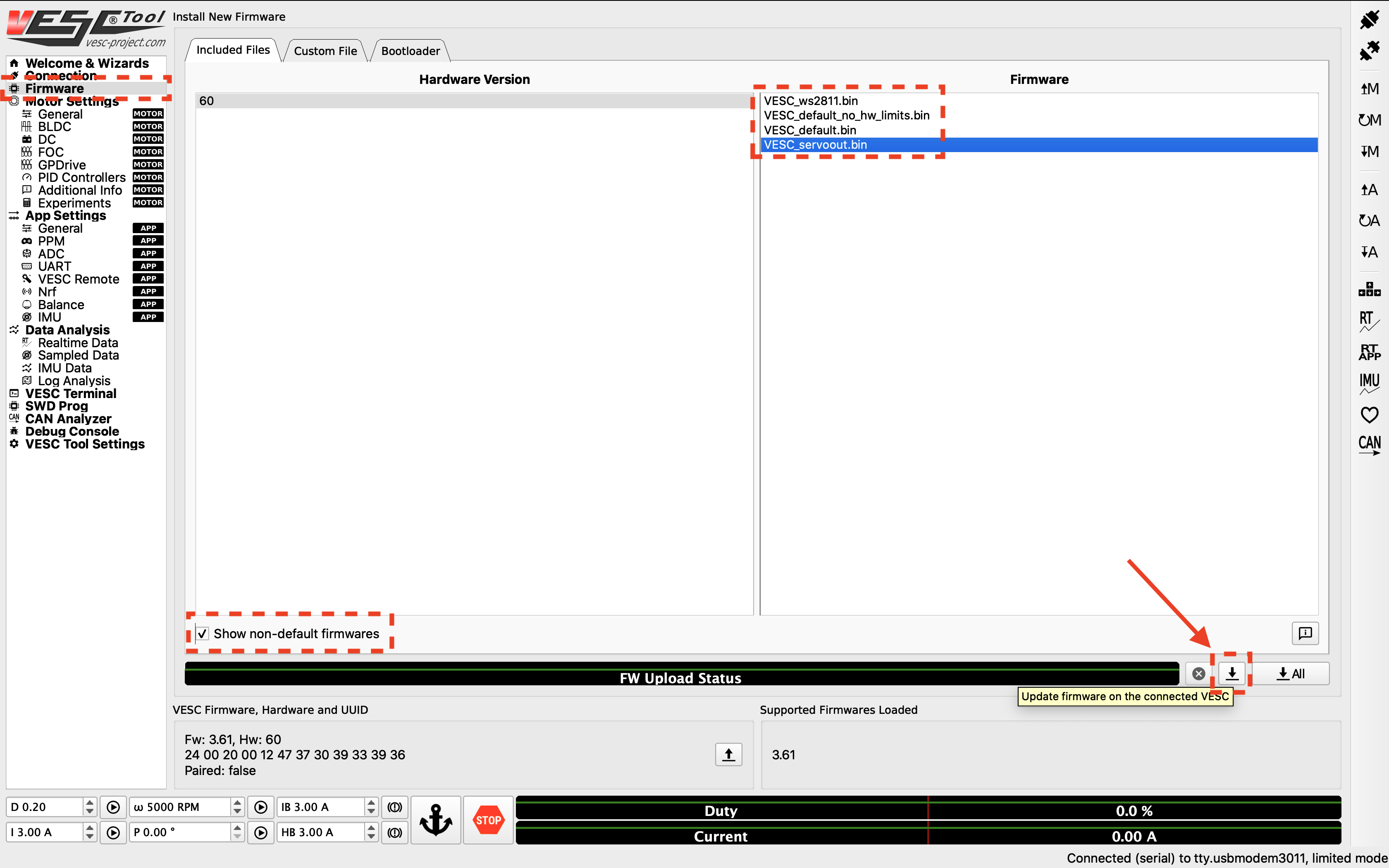
Update the firmware.
Once the firmware has been flashed and the VESC has reconnected, enable servo output from the PPM port (needed for steering) by going to App Settings > General > Enable Servo Output in the VESC Tool. After ticking the box, click the Write App Configuration button (the button with a down arrow and the letter “A”) on the right side of the screen to save the setting to the VESC. If you skip this step the change is not written to the device and servo output stays disabled.
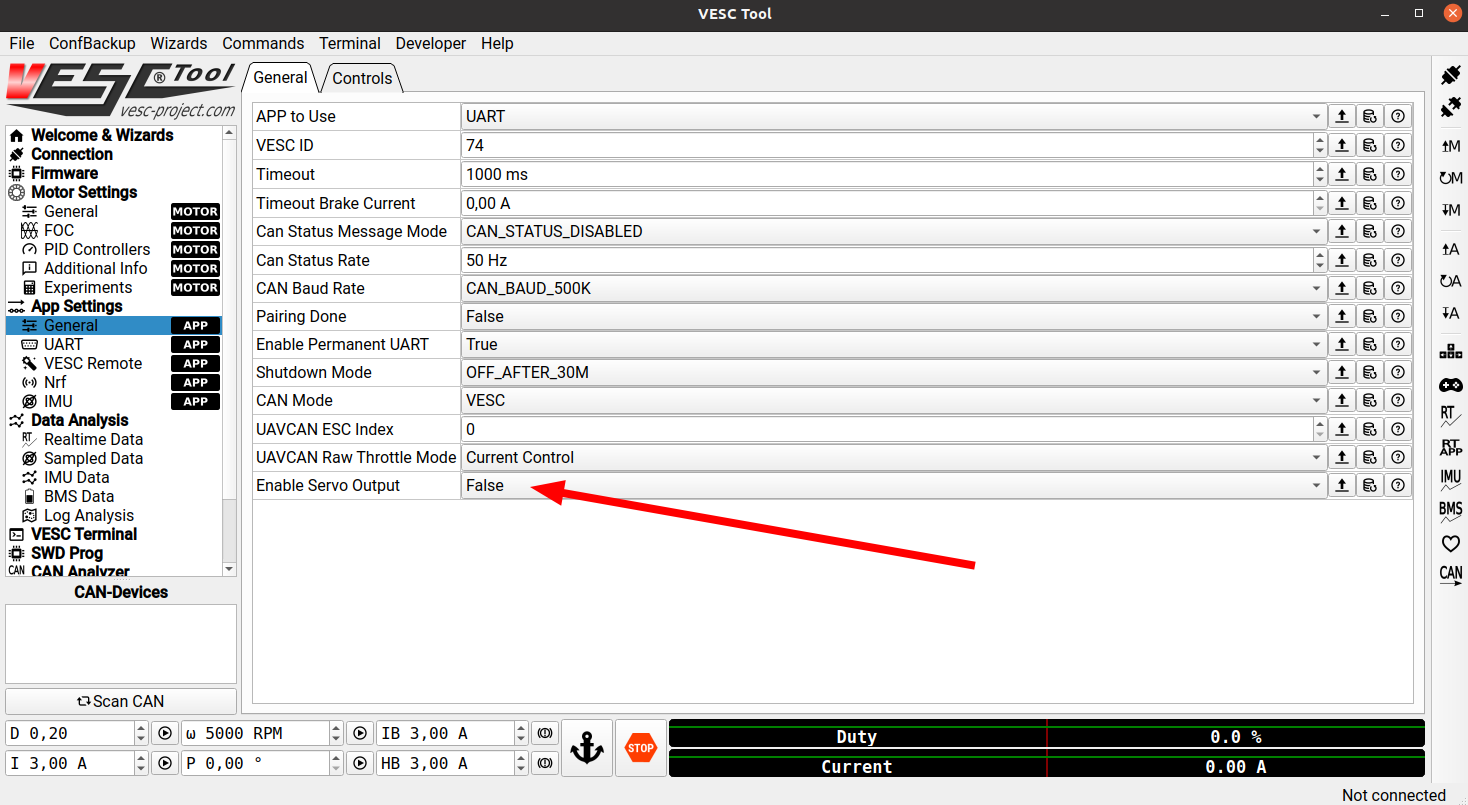
Enable Servo Output under App Settings > General, then click Write App Configuration to save it.
5. Uploading the Motor Configuration XML
After firmware update, Select Load Motor Configuration XML from the drop down menu and select the provided XML file from here . After the XML is uploaded, click on the Write Motor Configuration button (the button with a down arrow and the letter M) on the right side of the screen to apply the motor configuration. Note that in the future, you’ll have to press this button whenever you make a change in motor configuration.
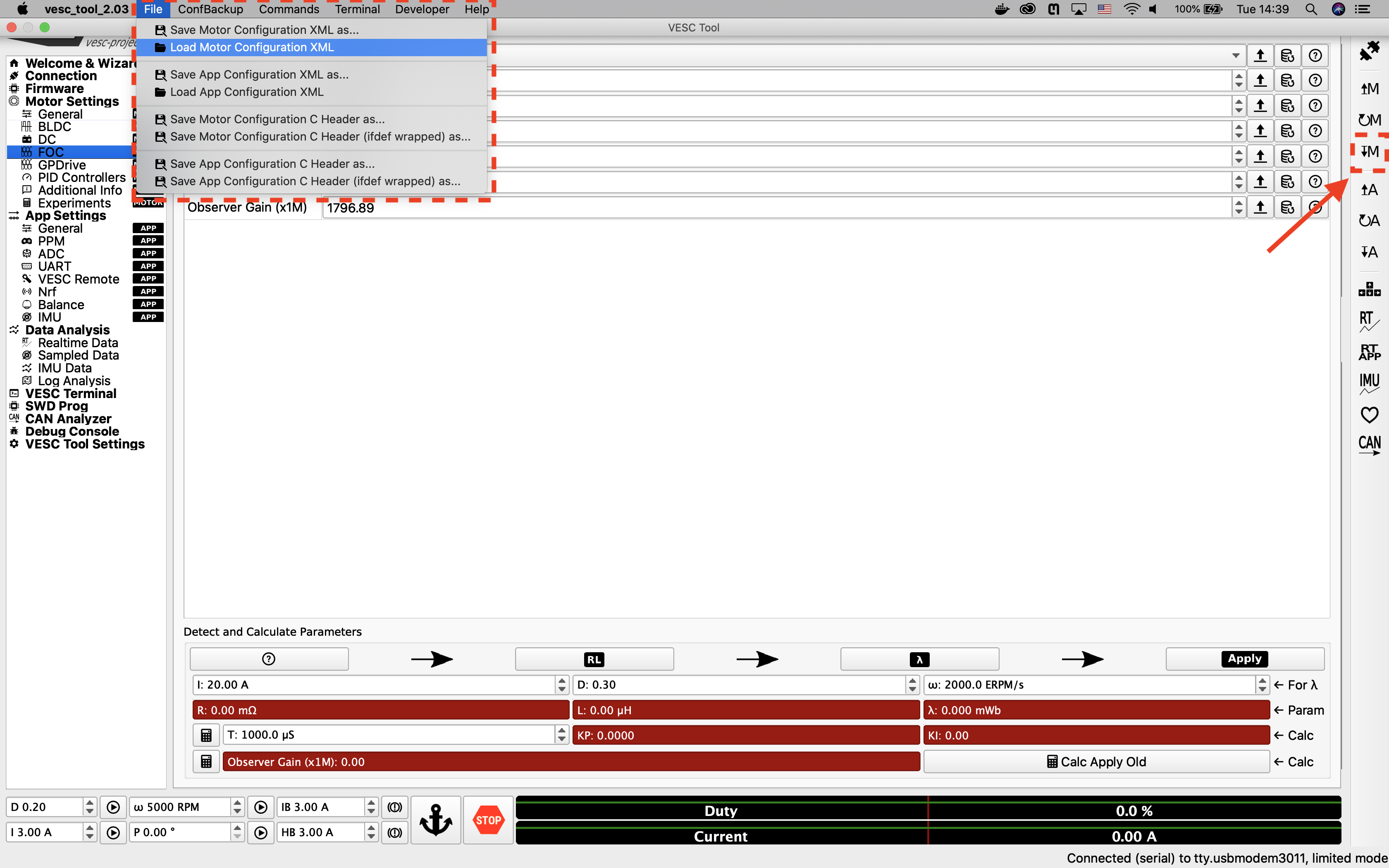
Upload the XML file.
6. Detecting and Calculating Motor Parameters
To detect and calculate the FOC motor parameters, navigate to the FOC tab under Motor Settings on the left. At the bottom of the screen, follow the direction of the arrows and click on the four buttons one by one, and follow the on screen prompt. Note that during the measuring process, the motor will make noise and spin, so make sure the wheels of your vehicle are clear.
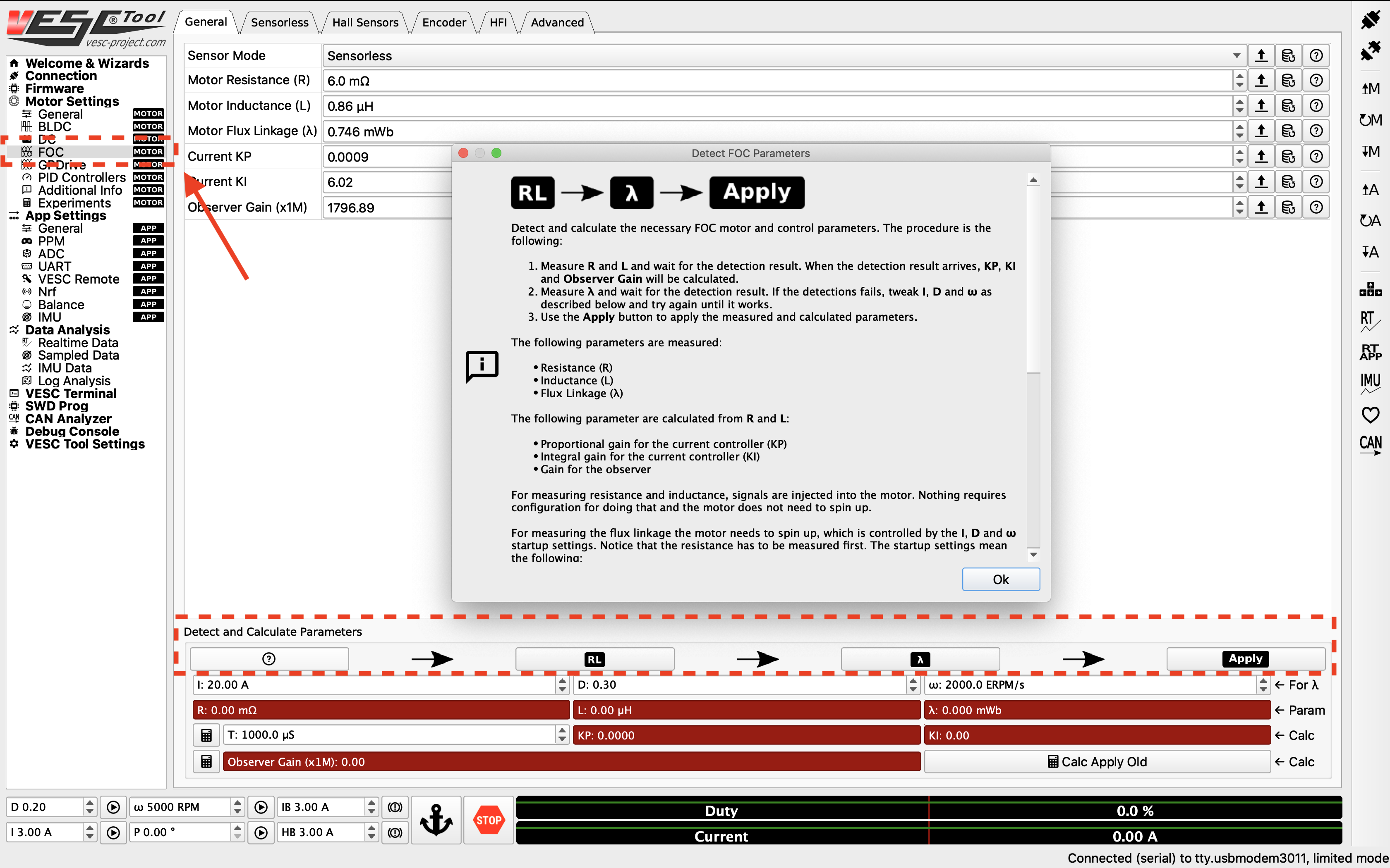
Detect the motor.
After the motor parameters are measured, the fields at the bottom of the screen should turn green. Click on the Apply button, and click the Write Motor Configuration button.
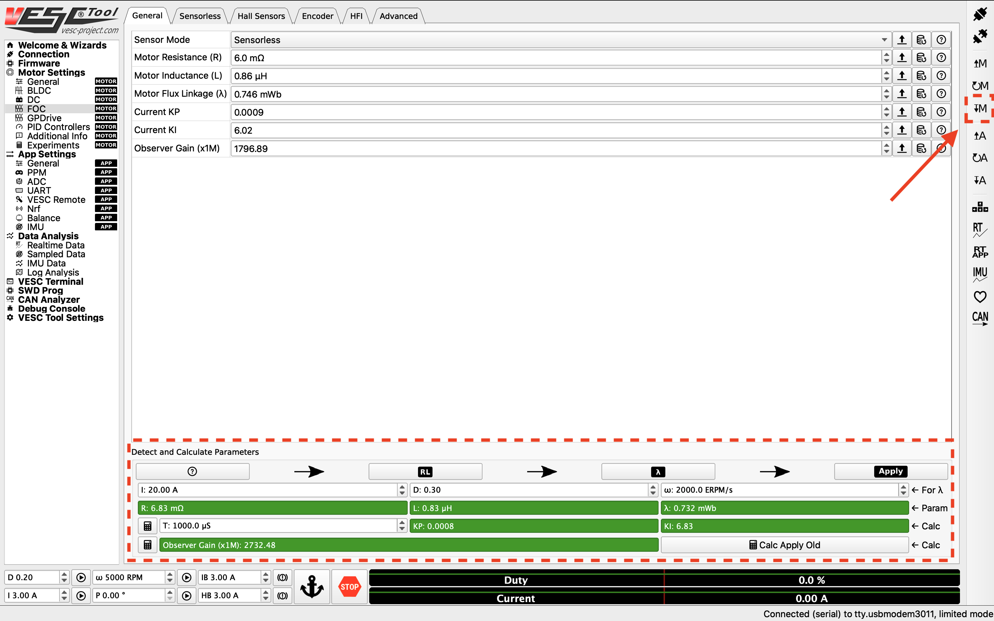
Apply the motor parameters.
7. Changing the Openloop Hysteresis and Openloop Time
Navigate to the Sensorless tab on top of the screen. Change the Openloop Hysteresis and Openloop Time to 0.01, and click the Write Motor Configuration button.
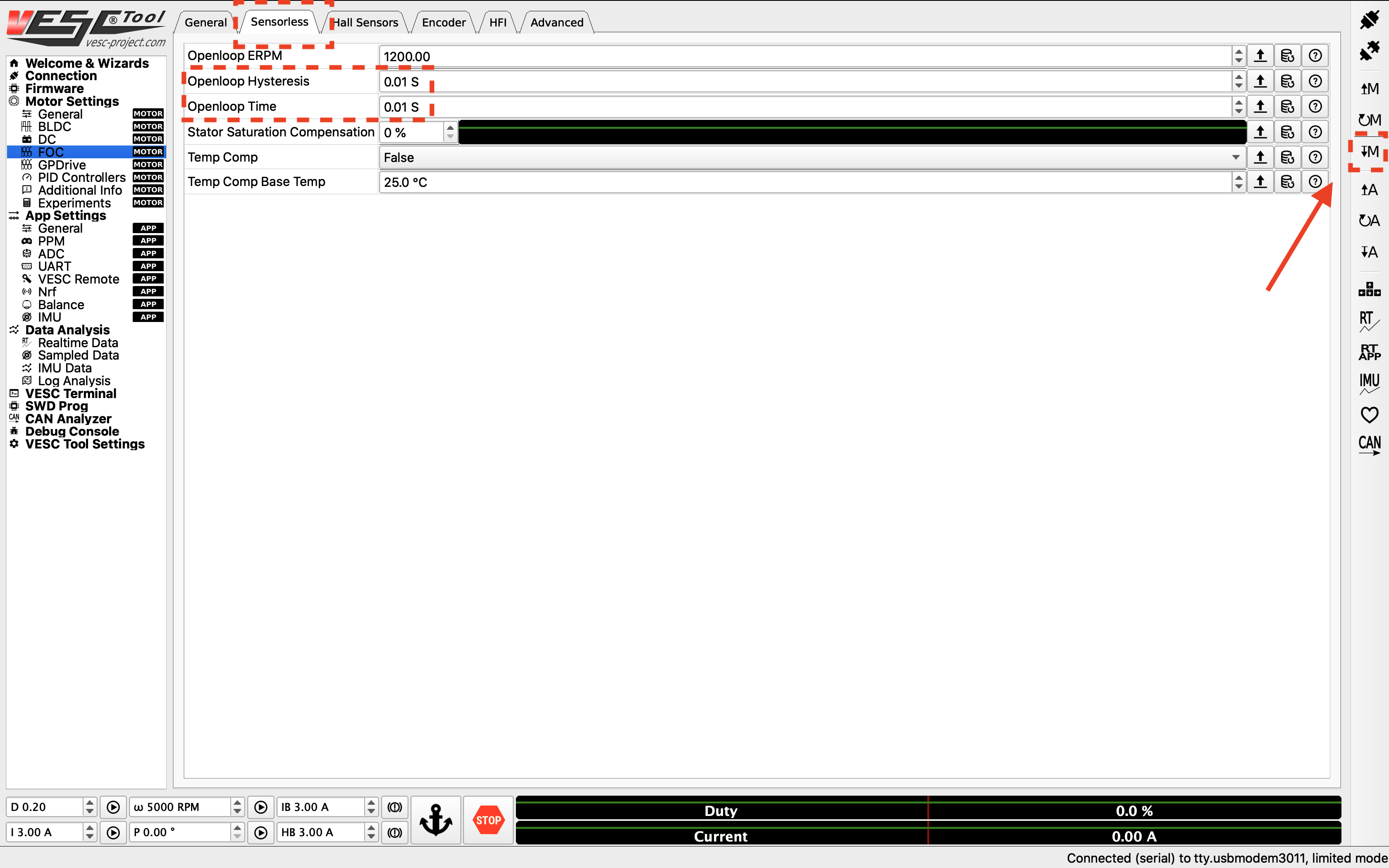
Change the openloop time.
8. Tuning the PID controller
Now you can start tuning the speed PID controller. To see the RPM response from the motor, navigate to the Realtime Data tab under Data Analysis on the left. Click Stream Realtime Data button on the right (the button with letters RT), and navigate to the RPM tab on the top of the screen. You should see RPM data streaming now.
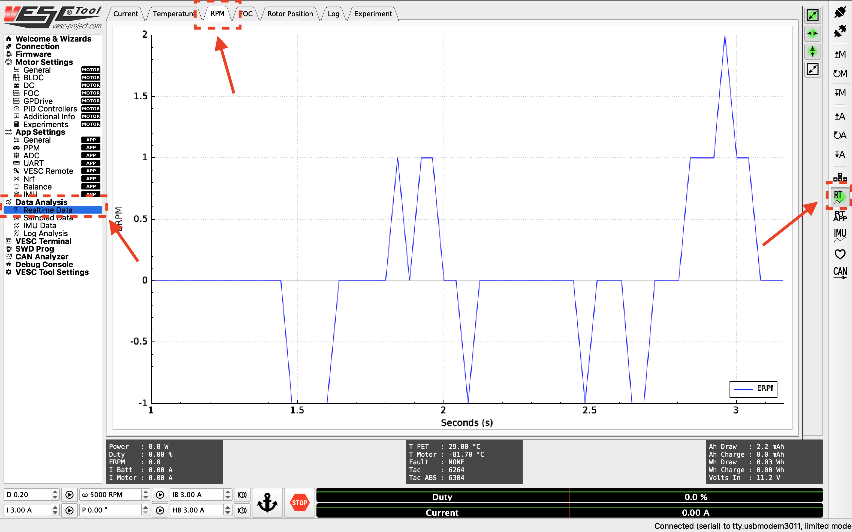
RPM data streaming.
To create a step response for the motor, you can set a target RPM at the bottom of the screen (values between 2000 - 10000 RPM). Click the play button next to the text box to start the motor. Note that the motor will spin, so make sure the wheels of your vehicle are clear from objects. Click the Anchor or STOP button to stop the motor.
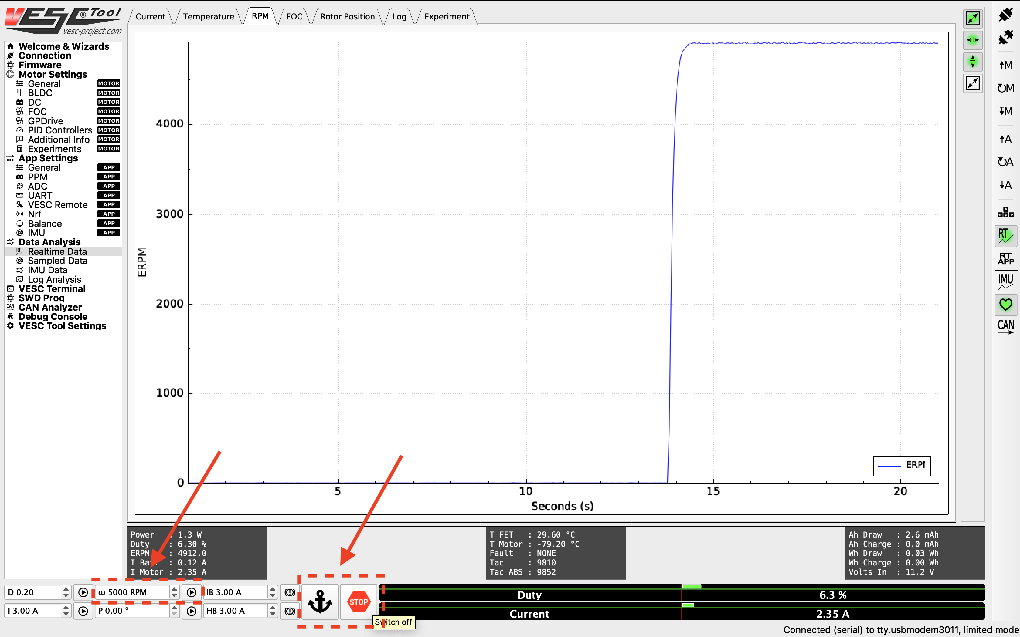
Step response from the motor.
You want to look for a clean step response that has a quick rise time and zero to very little steady state error. Adjust the gains accordingly by navigating to the PID Controllers tab under Motor Settings on the left, and change the Speed Controller gains. General rules of tuning PID gains apply. If you’re seeing a lot of oscillations, try changing the Speed PID Kd Filter.
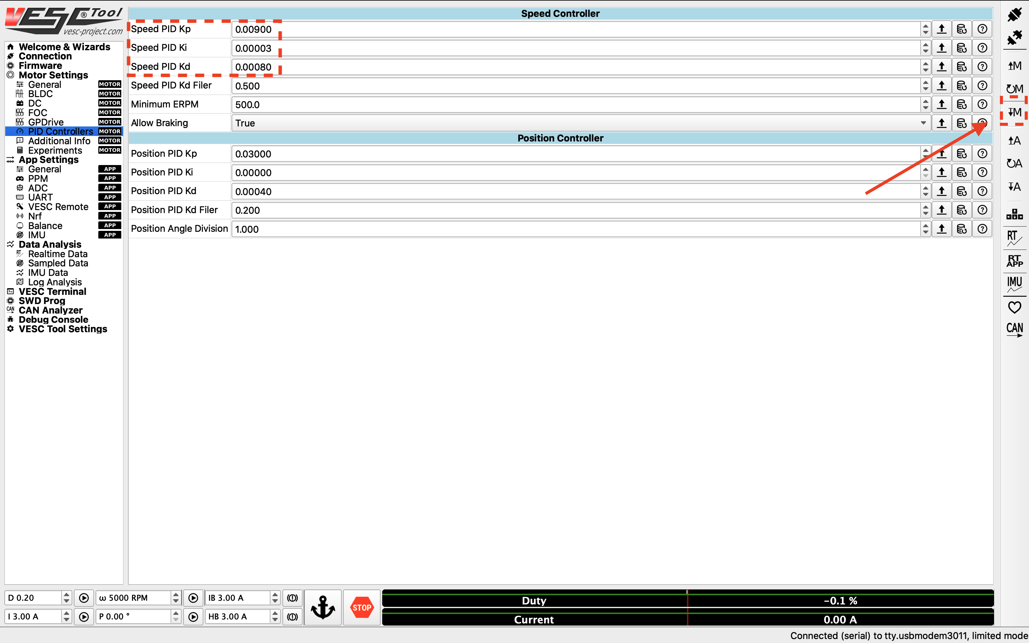
Adjusting PID gains.
9. Changing the hardware speed limit
By default, the motor configuration sets a safe top motor RPM. If you wish to change the hard limit set by the VESC firmware, you can go to Motor Settings > General, and change the max ERPM for forward and backwards rotations. You’ll also have to change the configuration file mentioned in the Odometry Tuning section in the software stack setup to change the software limit for your motor ERPM.
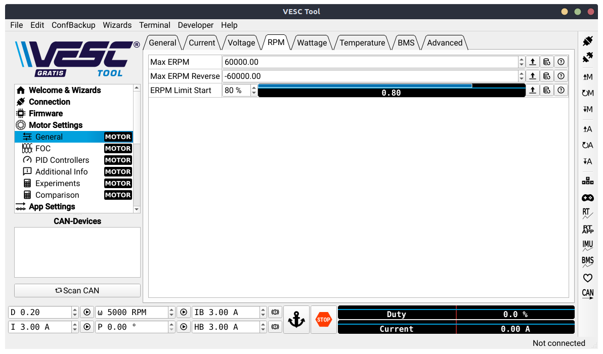
Changing the maximum ERPM.
Danger
Please see the Odometry Tuning section in the software stack setup to see how vehicle velocity is converted to ERPM for the motor to calculate a safe maximum erpm for your motor.